Function Settings
Function No. Code
1.00
Run/Stop-Forward/Reverse
Control
0001
External
Contacts
7.02
Multi-Function
Input Terminal 3
0010
Normally
Open Start
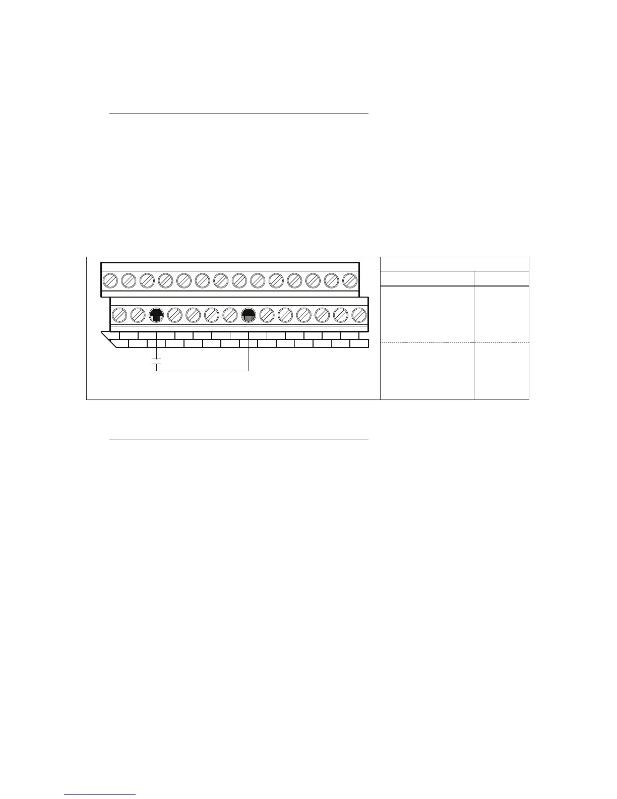
A7. 2-WIRE AND 3-WIRE START/STOP
A remote Start/Stop Switch or Contact can be used to start and stop the motor in lieu of the
RUN/STOP Key on the Keypad. The Start/Stop Switch or Contact can be connected for 2-Wire or 3-
Wire configuration, as described below.
2-WIRE START/STOP SWITCH OR CONTACT CONNECTION
2-Wire Start/Stop requires a maintained switch or contact. Connect the switch or contact to the
respective Multi-Function Input Terminal “1” – “7” and to Terminal “8” (common), as shown on Figure 32.
Set Run/Stop-Forward/Reverse Control (Function No. 1.00) to External Contacts (“0001”). Set the
respective Multi-Function Input Terminal (Function Nos. 7.00 – 7.06), which will be used for “Normally
Open Start”, to “0010”. In Figure 32, Multi-Function Input Terminal “3” has been arbitrarily chosen.
Note: Function code “0011” should not be programmed when using 2-Wire Start/Stop.
3-WIRE START/STOP SWITCH OR CONTACT CONNECTION
3-Wire Start/Stop requires momentary switches or contacts. Connect the normally open side of
the switch or contact to the respective Multi-Function Input Terminal “1” – “7”. Connect the normally
closed side of the switch or contact to the other respective Multi-Function Input Terminal “1” – “7”.
Connect the common of the switch or contacts to Terminal “8”. See Figure 33, on page 49.
Set Run/Stop-Forward/Reverse Control (Function No. 1.00) to External Contacts (“0001”). Set the
respective Multi-Function Input Terminal (Function Nos. 7.00 – 7.06), which will be used for “Normally
Open Start”, to “0010”. Set the respective Multi-Function Input Terminal (Function Nos. 7.00 – 7.06),
which will be used for “Normally Closed Stop”, to “0011”. In Figure 33, on page 49, Multi-Function Input
Terminals “1” and “2” have been arbitrarily chosen.
Notes: 1. When an MFIT (Terminal 2) is assigned code “0011”, the MFIT (Terminal 1) assigned code
“0010” automatically changes from maintained to momentary operation. 2. When using 3-Wire
Start/Stop, “Stop” will override “Start”, even if the Start Switch or Contact is kept in the “Start
position.