EasyManuals Logo

KB Electronics KBDA-24D User Manual

KB Electronics KBDA-24D
56 pages
To Next Page IconTo Next Page
To Previous Page IconTo Previous Page
Page #49 background imageLoading...
Page #49 background image
49
A8. SIGNAL FOLLOWING
An analog voltage (unidirectional or bidirectional), current, or PWM signal input can be used to control
motor speed in lieu of the Keypad or the Built-In Potentiometer. The drive output will linearly follow the
signal input. The inputs can be programmed for the desired gain, slope, offset, and response time. See
Analog Input Signal Operation (Function Group 9).
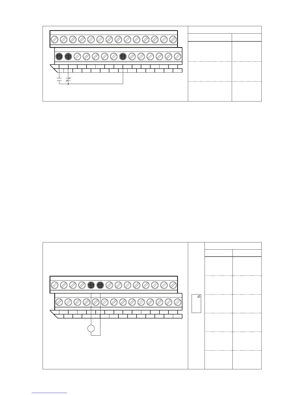
Analog Input 1 Connect the signal input to Terminal “19” and the common to Terminal “20”, as
shown in Figure 34. See settings for Analog Input 1 (Function Nos. 9.00 9.04). Set Frequency Control
(Function No. 2.00) to Analog Input 1 (“0002”). For unidirectional voltage input, set Analog Input 1 Type
(Function No. 9.03) to Unidirectional ((“0000”) (factory setting)). For bidirectional voltage input, set
Function No. 9.03 to Bidirectional (“0001”). See Table 14, on page 50, for Analog Input 1 electrical rat-
ings.
If the Analog Input 1 signal is higher than 5 Volts, use Trimpot MAX1 to attenuate it. Apply the maxi-
mum signal input and set the drive for full speed output and observe the display. Rotate Trimpot MAX1
counterclockwise until the drive output frequency begins to drop. Then rotate Trimpot MAX1 clockwise
until the display returns to the maximum output frequency.
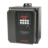
FIGURE 33 3-WIRE START/STOP SWITCH OR CONTACT CONNECTION AND FUNCTION SETTINGS
1
Start
15
TB1
Stop
Momentarily close the Start Switch or Contact to run the drive.
Momentarily open the Stop Switch or Contact to stop the drive.
32
16 17
5
4
18 19
7
6
20 21
9
8
22 23 28
11
10
24 25
1312
2726
14
Function Settings
Function No. Code
1.00
Run/Stop-Forward/Reverse
Control
0001
External
Contacts
7.00
Multi-Function
Input Terminal 1
0010
Normally Open
Start
7.01
Multi-Function
Input Terminal 2
0011
Normally Closed
Stop
FIGURE 34 – ANALOG INPUT 1 SIGNAL VOLTAGE FOLLOWING CONNECTION AND FUNCTION SETTINGS
-
+
144
16
15
1
TB1
1817
23 9
21
2019
56
2322
7 8
262524
10 11
2827
12 13
0 - ±5 Volts DC V
MAX1
Function Settings
Function No. Range/Code
2.00
Frequency
Control
0002
Analog
Signal 1
9.00
Analog Input 1
Gain
0 – 500
Set to the
Desired Gain
9.01
Analog Input 1
Slope
0000 or 0001
Positive or
Negative
9.02
Analog Input 1
Offset
0 – 100
Set to the
Desired Offset
9.03
Analog Input 1
Type
0000 or 0001
Unidirectional or
Bidirectional
9.04
Analog Input 1
Response Time
2 – 100
Set to the
Desired Time
OTHER FUNCTIONS AND FEATURES OF THE IODA

Table of Contents

Questions and Answers:

Question and Answer IconNeed help?

Do you have a question about the KB Electronics KBDA-24D and is the answer not in the manual?

KB Electronics KBDA-24D Specifications

General IconGeneral
BrandKB Electronics
ModelKBDA-24D
CategoryController
LanguageEnglish

Related product manuals