“The Right Control for Your Application.”
12095 NW 39 Street, Coral Springs, FL 33065-2516
KB Electronics, Inc. Phone: 954-346-4900; Fax: 954-346-3377
(A40288) - Rev. E - 6/6/2005 - Z3562E00 Page 17 of 20
Figure 23
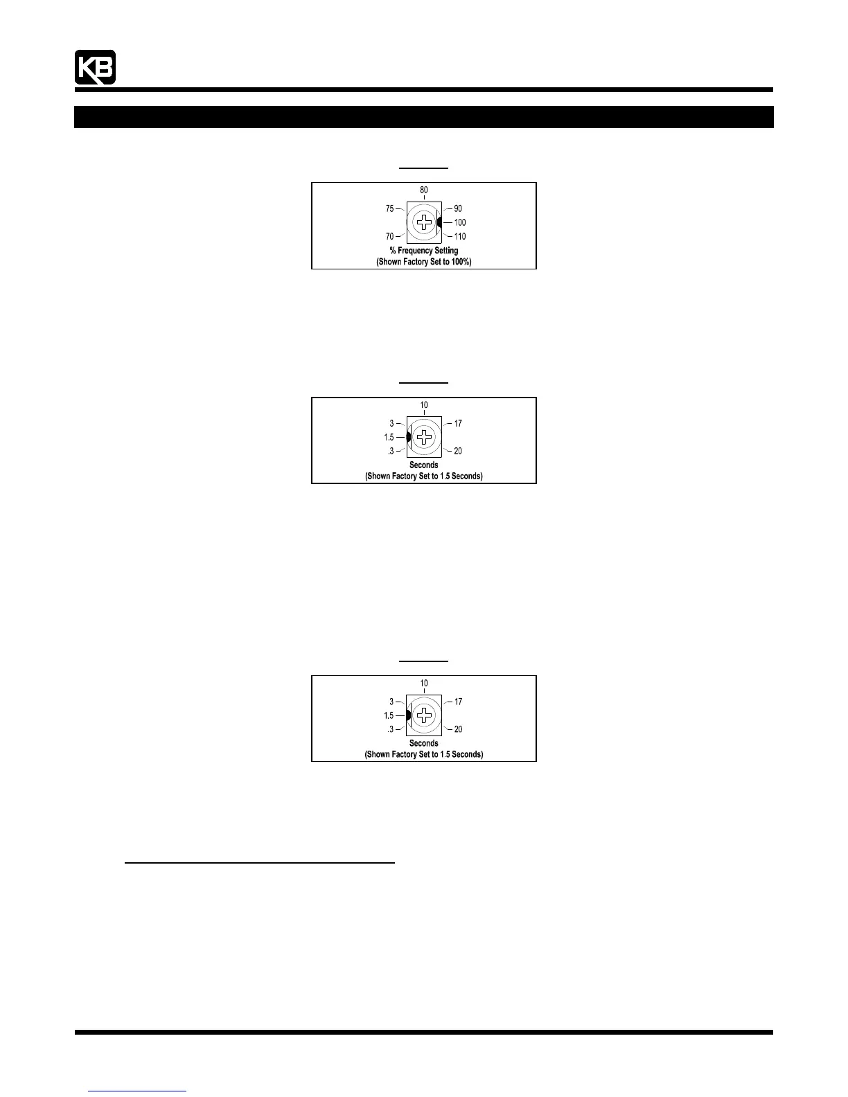
Maximum Speed Trimpot (MAX) Range
13.3 Acceleration (ACC): Sets the amount of time for the motor to accelerate from zero speed to full speed. The ACC Trimpot is factory
set to 1.5 seconds. For longer acceleration time, rotate the ACC Trimpot clockwise. For more rapid acceleration, rotate the ACC
Trimpot counterclockwise. See
Figure 24, on page XX.
Note: Rapid acceleration settings may cause the current limit circuit to activate, which will extend the acceleration time.
Figure 24
Acceleration Trimpot (ACC) Range
13.4 Deceleration (DEC/B): Sets the amount of time for the motor to decelerate from full speed to zero speed. The DEC/B Trimpot is
factory set to 1.5 seconds. For longer deceleration time, rotate the DEC/B Trimpot clockwise. For more rapid deceleration, rotate
the DEC/B Trimpot counterclockwise. See
Figure 25, on page XX.
Application Note: On applications with high inertial loads, the deceleration may automatically increase in time. This will slow down
the rate of speed of decrease to prevent the bus voltage from rising to the Overvoltage Trip point. This function is called
Regeneration Protection. It is recommended that for very high inertial loads that both the ACC and DEC/B Trimpots should
be set to greater than 10 seconds.
For rapid stopping, install the optional DBVF - Dynamic Brake Module (Part No. 9598). See
Section 3.5, on page XX.
Figure 25
Deceleration Trimpot (DEC/B) Range
13.5 Slip Compensation (COMP): Sets the amount of Volts/Hz to maintain set motor speed under varying loads. The COMP Trimpot is
factory set to 1.5 Volts/Hz, which provides excellent speed regulation for most motors. To increase the slip compensation, rotate the
COMP Trimpot clockwise. To decrease the slip compensation, rotate the COMP Trimpot counterclockwise. See
Figure 26, on page
XX
.
The slip compensation may be adjusted as follows:
1. Wire an AC ammeter in series with one motor phase.
2. Run the motor and set the unloaded speed to approximately 50% (900 RPM on 4-pole 1500/1725 RPM motors).
3. Using a tachometer, record the unloaded speed.
4. Load the motor to the nameplate rated current (AC Amps).
5. Adjust the COMP Trimpot until the loaded RPM is equal to the unloaded RPM.
6. The motor is now compensated to provide constant speed under varying loads.