“The Right Control for Your Application.”
12095 NW 39 Street, Coral Springs, FL 33065-2516
KB Electronics, Inc. Phone: 954-346-4900; Fax: 954-346-3377
(A40288) - Rev. E - 6/6/2005 - Z3562E00 Page 9 of 20
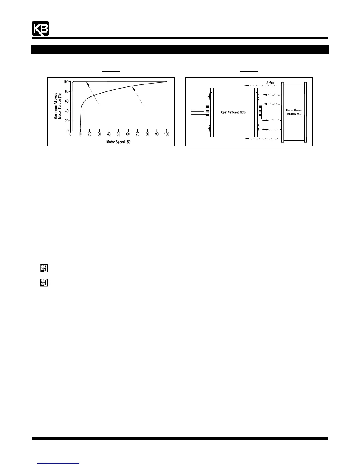
Figure 5
Maximum Allowed Motor Torque vs. Speed
Figure 6
Open Ventilated Motor with External Cooling
TEFC and Open Ventilated Motors
Fan Cooled
and TENV Motors
Inverter Duty
4.2 Electronic Motor Overload Protection: The drive contains Modified I
2
t Overload Protection.* Part of this function consists of a
Current Limit (CL) circuit, which limits the drive current to a factory preset level of 160% of the rated drive current. The CL Trimpot
is used to recalibrate the drive current from 60% thru 200%. The Power Start™ circuit provides an overshoot function that allows
most motors to develop more than 200% of starting torque and breakdown torque.
Standard I
2
t is undesirable because it causes nuisance tripping. It allows a very high motor current to develop and will turn the drive
off after a short period of time. KB's RMS Current Limit Circuit avoids this nuisance tripping while providing maximum motor
protection.
If the motor is overloaded to 120% of full load (75% of the CL setting), the I
2
t Timer starts. If the motor continues to be overloaded
at the 120% level, the timer will shut down the drive after 30 minutes. If the motor is overloaded to 160% of full load, the drive will
trip in 6 seconds.
* UL approved as an overload protector for motors.
5 FINGER-SAFE COVER
The drive is designed with an IP-20 Finger-Safe Cover which provides protection against accidental contact with high voltage.
WARNING! Disconnect main power when removing or installing the Finger-Safe Cover.
WARNING! To prevent accidental contact with high voltage, it is required that the Finger-Safe Cover be properly installed
onto the drive after all wiring and setup is complete. It offers protection against electric shock which limits the potential liability
to the equipment manufacturer and installer.
5.1 Removing the Finger-Safe Cover: The Finger-Safe Cover may have to be removed before wiring the drive or setting selectable
jumpers. All trimpots can be readjusted with the Finger-Safe Cover installed. Notice the orientation of the Finger-Safe Cover before
removing it.
Note: The Finger-Safe Cover (except that of the KBVF-21D) is designed with a removable panel (on the trimpots side) which must be removed for
installation of optional accessories SIVFR Signal Isolator and Run/Fault Relay (Part No. 9597) or Multi-Speed Board (Part No. 9503). Complete
instructions are provided with the accessories.
Model KBVF-21D: Designed with three "push-ins" (instead of retainer clips) located where the Finger-Safe Cover aligns with the
base. To remove the cover, gently press at the three push-ins until the cover disengages from the base.
Models KBVF-22D, 13, 23, 23D, 14, 24, 24D, 26D: To remove the Finger-Safe Cover, gently lift up on the four retainer clips until
the cover disengages from the base. See
Figures 2 and 3, on pages XX-XX.
Note: On Model KBVF-26D, the inner bus capacitor support bracket should not be removed.
5.2 Installing the Finger-Safe Cover: To install the Finger-Safe Cover, be sure to properly align the retainer clips or push-ins. Gently
push the Finger-Safe Cover onto the base until the retainer clips or push-ins are fully engaged with the base.