“The Right Control for Your Application.”
12095 NW 39 Street, Coral Springs, FL 33065-2516
KB Electronics, Inc. Phone: 954-346-4900; Fax: 954-346-3377
(A40288) - Rev. E - 6/6/2005 - Z3562E00 Page 16 of 20
12 DIAGNOSTIC LEDs
The drive contains two diagnostic LEDs to display the drive's operational status. See Figure 4, on page XX, for the location of the "PWR"
and "ST" LEDs.
12.1 Power On (PWR): The "PWR" LED will illuminate green when the AC line is applied to the drive.
12.2 Status LED (ST): The "ST" LED is a tricolor LED which provides indication of a fault or an abnormal condition. The information
provided can be used to diagnose an installation problem such as incorrect input voltage, overload condition, and drive output
miswiring. It also provides a signal which informs the user that all drive and microcontroller operating parameters are normal. Table
4, on page XX
, summarizes the "ST" LED functions.
Note: The drive is factory set to the Automatic Start Mode. For Manual Start/Rest, see Section 9.6, on page XX.
Table 4
Drive Operating Condition and Status LED Indicator
Drive Operating Condition Flash Rate
1
and LED Color
Normal Operation Slow Flash Green
Overload
(120% - 160% Full Load)
Steady Red
2
I
2
t
(Drive Timed Out)
Quick Flash Red
2
Short Circuit Slow Flash: Red
Undervoltage
Quick Flash Red / Yellow
3
Overvoltage
Slow Flash Red / Yellow
3
Stop Steady Yellow
Notes: 1. Slow Flash = 1 second on and 1 second off. Quick
Flash = 0.25 second on and 0.25 second off. 2. In Manual Start
Mode, when the Overload is removed, before the I
t times out
and trips the drive, the “ST” LED will flash green. 3. In Manual
Start Mode, when the Undervoltage or Overvoltage condition is
corrected, the “ST” LED will flash Red / Yellow / Green.
13 TRIMPOT ADJUSTMENTS
The drive contains trimpots which are factory set for most applications. See Figure 4, on page XX, for the location of the trimpots and their
approximate factory calibrated positions. Some applications may require readjustment of the trimpots in order to tailor the drive for a
specific requirement. The trimpots may be readjusted as described below.
WARNING! If possible, do not adjust trimpots with the main power applied. If adjustments are made with the main
power applied, an insulated adjustment tool must be used and safety glasses must be worn. High voltage exists in this drive.
Fire and/or electrocution can result if caution is not exercised. Safety Warning, on page XX, must be read and understood
before proceeding.
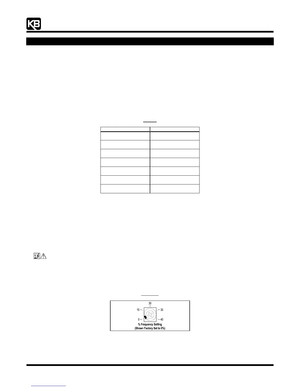
13.1 Minimum Speed (MIN): Sets the minimum speed of the motor. The MIN Trimpot is factory set to 0% of frequency setting. For a
higher minimum speed setting, rotate the MIN Trimpot clockwise. See
Figure 22, on page XX.
Figure 22
Minimum Speed Trimpot (MIN) Range
13.2 Maximum Speed (MAX): Sets the maximum speed of the motor. The MAX Trimpot is factory set to 100% of frequency setting. For
a higher maximum speed setting, rotate the MAX Trimpot clockwise. For a lower maximum speed setting, rotate the MAX Trimpot
counterclockwise. See
Figure 23, on page XX.