11
Note: Do not connect motor armature leads to F1 and F2 quick-connect terminals. Do
not use F+ and F- terminals of Terminal Block TB2 for any purpose other than to power
the field of a shunt wound motor.
E. Half Voltage Field Connection (Shunt Wound Motors Only) – Wire the motor field
leads to F+ terminal of Terminal Block TB2 and L1 terminal of Terminal Block TB1, as
shown in Figure 6, on page 10 and as described in Table 4.
Note: Do not connect motor armature leads to F+ and F- terminal of Terminal Block TB2
or to F1 and F2 quick-connect terminals. Do not use F+ and F- terminals of Terminal
Block TB2 for any purpose other than to power the field of a shunt wound motor.
F. Remote Main Speed Potentiometer Connection – The control is supplied with a
prewired Main Speed Potentiometer mounted on the front cover for unidirectional forward
operation of the motor as shown in Figure 7.
To rewire the Main Speed Potentiometer for a different direction or to operate the control
from a remote potentiometer (5k), remove the white, orange and violet potentiometer
leads from P1, P2 and P3 terminals and connect it as described below. The leads may
be taped and left inside the control. The potentiometer assembly may be removed if a
watertight seal is used to cover the hole in the front cover.
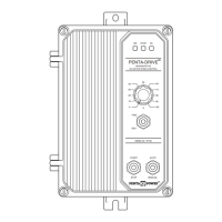
1. Unidirectional Forward
Operation – Connect the Main
Speed Potentiometer high side
to +15V terminal, wiper to SIG
terminal and low side to COM
terminal, as shown in Figure 7.
Rotating the Main Speed
Potentiometer clockwise will
increase motor speed in the for-
ward direction. Rotating the
Main Speed Potentiometer
counterclockwise will decrease motor speed.
Note: Jumper J5 must be set to the
“15V” position.
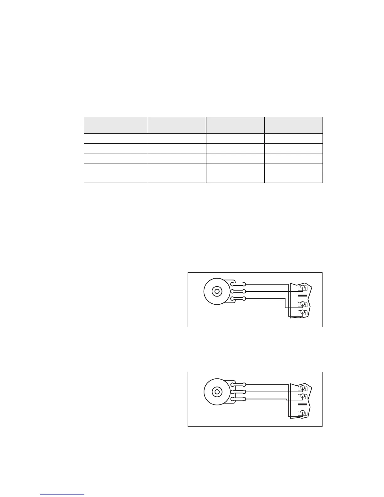
2. Unidirectional Reverse
Operation – Connect the Main
Speed Potentiometer high side
to -15V terminal, wiper to SIG
terminal and low side to COM
terminal, as shown in Figure 8.
Rotating the Main Speed
Potentiometer clockwise will
increase motor speed in the
reverse direction. Rotating the
Main Speed Potentiometer
counterclockwise will decrease motor speed.
Note: Jumper J5 must be set to the
“15V” position.
F+ and L1
Field Voltage
(Volts DC)
Field Connections
AC Line Voltage
(Volts AC)
Armature Voltage
(Volts DC)
115 0 – ±90
115
208/230
208/230
208/230
0 – ±90
0 – ±90
0 – ±180
0 – ±180
100
50
200
100
100
F+ and F-
F+ and L1
F+ and F-
F+ and L1
TABLE 4 – FIELD CONNECTION (SHUNT WOUND MOTORS ONLY)
 Loading...