12
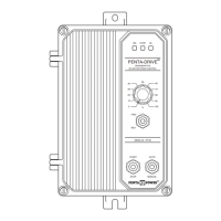
3. Bidirectional Operation –
Provides forward and reverse
operation using the Main Speed
Potentiometer. Connect the
Main Speed Potentiometer high
side to +15V terminal, wiper to
SIG terminal and low side to
-15V terminal, as shown in
Figure 9. Zero motor speed will
now be located at 50% rotation.
Rotating the Main Speed Potentiometer clockwise will increase motor speed in the
forward direction. Rotating the Main Speed Potentiometer counterclockwise will
increase motor speed in the reverse direction.
Note: Jumper J5 must be set to the
“15V” position.
Note: If the motor runs in the opposite direction than is desired, disconnect power
and either reverse the high side and low side of the Main Speed Potentiometer wires
or reverse the motor leads to M1 and M2 terminals of Terminal Block TB1.
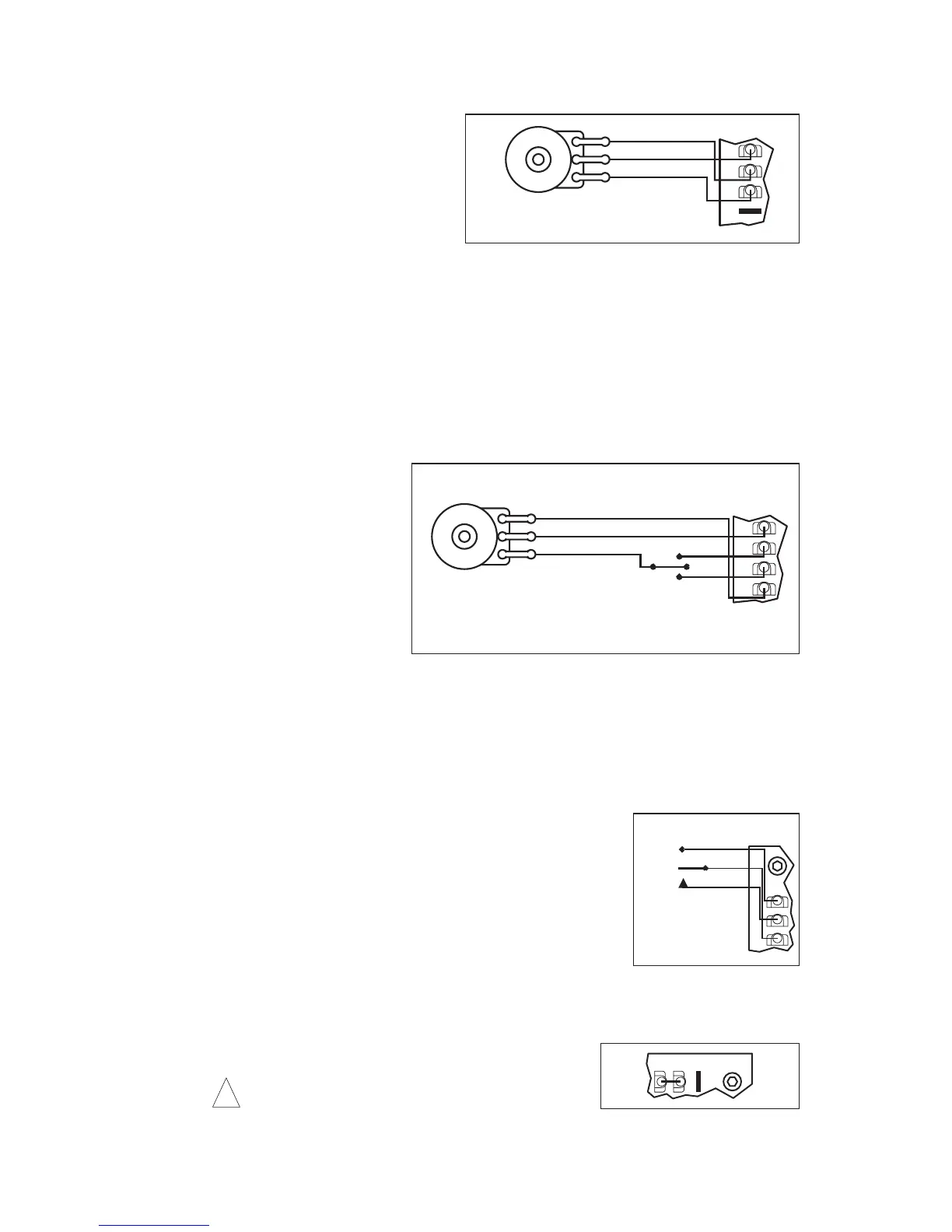
4. Bidirectional
Operation with
Reversing Contacts –
Connect the Main
Speed Potentiometer
high side to the center
of the switch (type ON-
OFF-ON, SPDT switch
with center off position),
wiper to SIG terminal
and low side to COM
terminal. Connect the
“forward” side of the
switch to the +15V ter-
minal and the “reverse”
side of the switch to the -15V terminal, as shown in Figure 10. Rotating the Main
Speed Potentiometer clockwise will increase motor speed in the direction selected by
the switch. Rotating the Main Speed Potentiometer counterclockwise will decrease
motor speed.
Note: Jumper J5 must be set to the “15V” position.
G. Remote Start/Stop Switch Connection – The control is sup-
plied with a prewired Start/Stop Switch, mounted on the front
cover. To operate the control from a remote Start/Stop Switch
(type (ON)-OFF-ON, SPDT), remove the white, black, and
red wires from START, RET and STOP terminals. The leads
may be taped and left in the control. The switch assembly
may be removed if a watertight seal is used to cover the hole
in the front cover. Connect the remote Start/Stop Switch
wires to START (momentary), RET (common) and STOP
(constant) terminals, as shown in Figure 11. After applying
power, momentarily set the Start/Stop Switch to the “START”
position. The motor will run at the set speed of the Main
Speed Potentiometer. To stop the motor, set the
Start/Stop Switch to the “STOP” position.
Note: To eliminate the Start/Stop function, connect
START and RET terminals with the jumper that is pro-
vided, as shown in Figure 12.
CAUTION! Eliminating the Start/Stop function
using a jumper will cause the motor to run at the
Main Speed Potentiometer setting when the AC line is applied.
 Loading...