14
the motor armature voltage. If the tach-generator polarity is reversed, the motor will
accelerate to full speed and the Main Speed Potentiometer will not control speed. Tach-
generator feedback can greatly improve speed regulation and dynamic response.
Note: When using a tach-generator, the IR trimpot should be set fully counterclockwise.
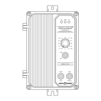
Note: The tach-generator input is designed for 7 Volt or 50 Volt per 1000 RPM tach-gen-
erators used with 1800 RPM motors. For a tach-generator other than 7 Volt or 50 Volt
per 1000 RPM or for motors other than 1800 RPM, an external 1/2 Watt resistor (R
T
)
must be installed. Install R
T
in series with the tach-generator, as shown in Figure 16.
Jumper J3 must be set to the “7V” position.
The value of R
T
in Ω can be calculated using the following formula:
R
T
= (4.37 X V
T
X S) - 55000 Where V
T
is the tach-generator voltage (in Volts per 1000
RPM) and S is the base speed of the motor (in RPM).
Example:
Suppose you have a 20 Volt per 1000 RPM tach-generator with a 3600 RPM motor.
R
T
= (4.37 X 20 X 3600) - 55000 = 259640
Choose the closest 1/2 Watt resistor value, which is 240000 (240k) or 270000 (270k).
Readjustment of the MAX trimpot may be necessary to achieve the desired maximum
output voltage.
III. SETTING SELECTABLE JUMPERS
The KBRC-240D has selectable jumpers which must be set before the control can be used.
See Figure 1, on page 7, for location of jumpers.
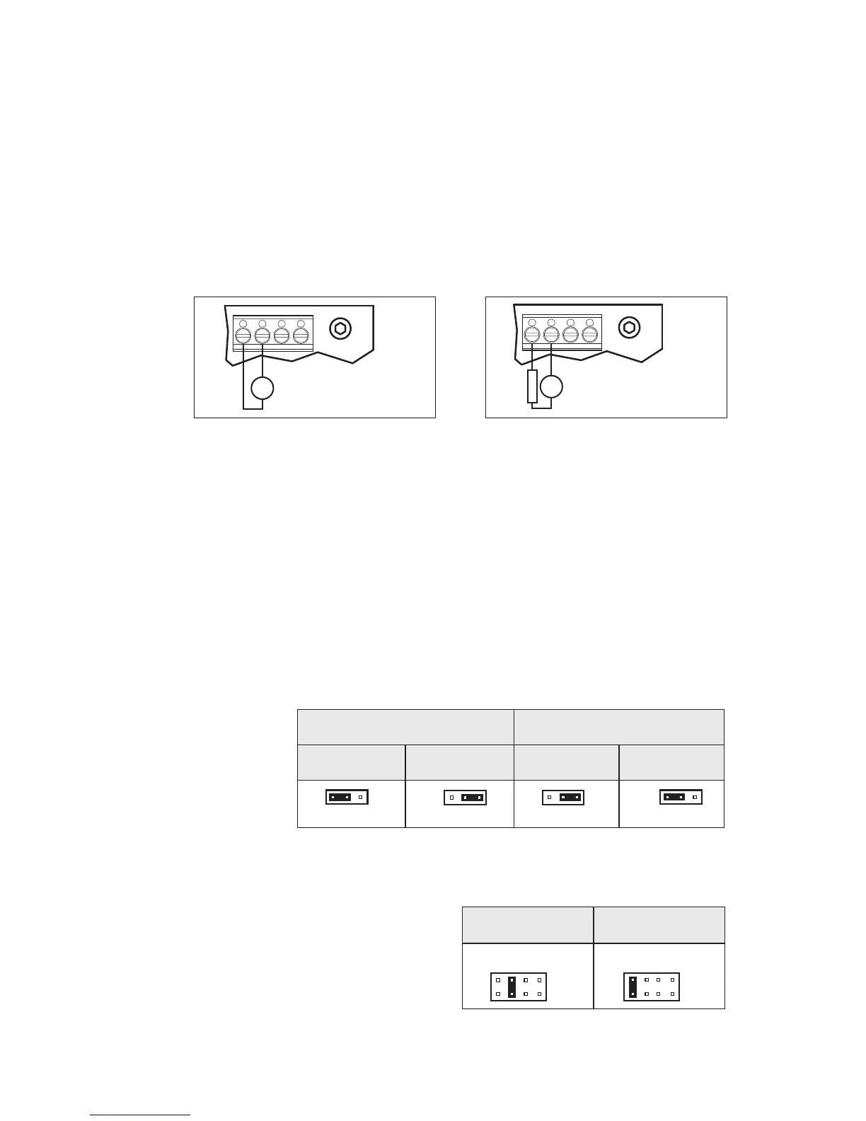
A. AC Line Input
Voltage
Selection (J1
and J2) –
Jumpers J1
and J2 are
both factory
set to the
“230V” position
for 208/230
Volt AC line input. For 115 Volt AC line
input, set
both Jumpers J1 and J2 to the
“115V” position. See Figure 17.
B. Motor Voltage Selection (J3) – Jumper
J3 is factory set to the “A180” position for
180 Volt motors. For 90 Volt motors, set
Jumper J3 to the “A90” position. See
Figure 18.
 Loading...