6
Potentiometer rotation or input signal. In the Non-Linear Torque mode (NL), the torque is var-
ied by the Main Speed Potentiometer or input signal, and remains constant throughout the
motor’s entire speed range. In addition, Regenerate-to-Stop (RTS) or Coast-to-Stop (CTS)
stop modes are also provided.
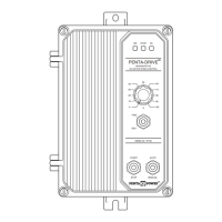
Standard front panel features of the KBRC-240D include diagnostic LEDs (for Power On,
Stop and Overload), a Start/Stop Switch and a Main Speed Potentiometer. Other features
include Barrier Terminal Blocks (facilitates wiring of the AC line, motor armature and field,
tach-generator and run relay), adjustable trimpots (OFFSET, FACC, RACC, MAX, FWDCL,
REVCL, IR, RESP, DB and TCL), selectable jumpers (AC line voltage, motor voltage or tach
feedback, motor current, analog input voltage, control mode, torque mode, current limit
mode, stopping mode, run relay output contacts and enable) and PC Board mounted LEDs
(Power On, Overload, Forward Enable and Reverse Enable).
Optional accessories for the KBRC-240D include a Forward-Stop-Reverse Switch,
Auto/Manual Switch, Power On/Off Switch and a Signal Isolator. Quick-connect terminals are
provided for easy installation of all accessories. See Section X, on page 22.
10
Parameter Specification
Forward Acceleration Trimpot (FACC) Range (Seconds)
Forward Current Limit Trimpot (FWDCL) Range (% Range Setting)
Factory
Setting
AC Line Input Voltage (Volts AC, ±10%, 50/60 Hz) 115 and 208/230
Armature Voltage Range at 115 Volts AC Line (Volts DC) 0 – ±90
230
—
Armature Voltage Range at 208/230 Volts AC Line (Volts DC)
0 – ±90
1
, 0 – ±180
0 – ±180
Field Voltage at 115 Volts AC Line (Volts DC) 100/50 —
Field Voltage at 208/230 Volts AC Line (Volts DC) 200/100 —
Signal Following Input (Non-Isolated
2
) Range (Volts DC)
0 – ±10, 0 – ±15 0 – ±15
Signal Following Linearity (% Base Speed) 1 —
Line Regulation (% Base Speed) ±0.5 —
Armature Feedback Load Regulation (% Base Speed) ±1 —
Tach-Generator Feedback Load Regulation (% Set Speed) ±1 —
150
Maximum Load Capacity (% for 2 Minutes) 150 —
Current Ranges (Amps DC) 1.7, 2.5, 5, 7.5, 10
Speed Range (Ratio) 50:1 —
Operating Temperature Range (°C) 0 – 45 —
Offset Trimpot (OFFSET) Range (% Base Speed) 0 – ±10 0
Reverse Acceleration Trimpot (RACC) Range (Seconds) 0.2 – 15 1
0.2 – 15 1
0 – 200
Reverse Current Limit Trimpot (REVCL) Range (% Range Setting) 0 – 200 150
IR Compensation Trimpot (IR) Range at 90 Volts DC Output (Volts DC at Full Load) 0 – 15 —
IR Compensation Trimpot (IR) Range at 180 Volts DC Output (Volts DC at Full Load) 0 – 30 10
TABLE 1 – GENERAL PERFORMANCE SPECIFICATIONS
Maximum Speed Trimpot (MAX) Range (% Base Speed) 70 – 110 100
Deadband Trimpot (DB) Range (% Base Speed) 0 – ±3 0.5
Timed Current Limit Trimpot (TCL) Range (Seconds) 0 – 15 5
TABLE 2 – ELECTRICAL RATINGS
1, (0.75)
Maximum
Horsepower Rating
HP, (kW)
AC Line Input Voltage
(±10%, 50/60 Hz)
(Single Phase Volts AC)
Maximum Output
Load Current
(Amps DC)
115
Maximum AC Line
Input Current
(Amps AC)
15
Nominal Output
Voltage
(Volts DC)
0 – ±90 11
208/230
208/230
15
15
0 – ±180
0 – ±90
1
11
11
2, (1.5)
1, (0.75)
Notes: 1. Step-down operation: Motor may have reduced brush life. Consult motor manufacturer.
2. Requires an isolated signal. If a non-isolated signal is used, install the Signal Isolator SIRC (P/N 8842).
Note: 1. Step-down operation: Motor may have reduced brush life. Consult motor manufacturer.
 Loading...