Note: If the IR compensation is too high, unstable (oscillatory) operation will result. If the
control is used with a DC tach-generator, the IR trimpot should be set fully counterclock-
wise.
To Calibrate the IR Trimpot:
1. Run the motor at approximately 30 - 50% of rated speed at no load and measure the
actual speed.
2. Load the motor to the rated current. Adjust the IR trimpot so that the loaded speed is
the same as the unloaded speed measured in step 1.
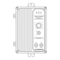
F. Response (RESP): Sets the relative response of the control.
The RESP trimpot is factory set to 50% rotation. For faster
response, rotate the RESP trimpot clockwise. For slower
response, rotate the RESP trimpot counterclockwise. See
Figure 40. Note: If response is made too rapid, unstable, oscil-
latory operation may result.
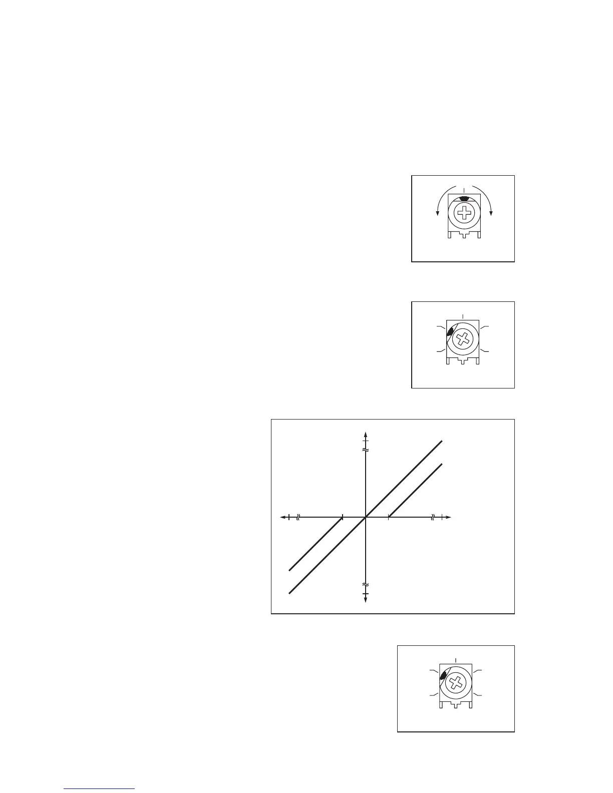
G. Deadband (DB): Sets the amount of Main Speed
Potentiometer rotation required to initiate control voltage out-
put. The DEADBAND trimpot is factory set to 0.5% of base
speed. For more deadband, rotate he DB trimpot clockwise.
For less deadband, rotate the DB trimpot counterclockwise.
See Figure 41 and Figure 42.
The DB trimpot also determines the amount of delay that will
occur before regeneration begins. (Regeneration occurs
when the applied load torque is in the same direction as the
motor rotation.)
To Calibrate the DB Trimpot:
1. Set the Main Speed Potentiometer to the zero speed
position.
2. Set the DB trimpot fully
counterclockwise.
3. Adjust the DB trimpot
until motor hum is elimi-
nated.
Note: If the DB trimpot is set
too low (counterclockwise
position), the motor may
oscillate between forward
and reverse directions.
Adjust the DB trimpot clock-
wise until the instability dis-
appears. (Oscillation may
also occur due to the setting
of the RESP trimpot. See
Section VIIIF.)
H. Timed Current Limit (TCL) – Sets the time for the control
to shut down after being in current limit (provides electron-
ic motor burnout protection). The TCL trimpot is factory set
for 5 seconds. To increase the TCL setting, rotate the TCL
trimpot clockwise. To decrease the TCL setting, rotate the
TCL trimpot counterclockwise. If the control remains in CL
for a predetermined amount of time (set by the TCL trimpot
and if Jumper J8 is in the “TCL” position), the control will
shut down.
21
 Loading...