15
Note: If Jumper J3 is set to the “T7” or “T50” position, a tach-generator must be wired to
Terminal Block TB3. If a tach- generator is not used, Jumper J3 must be in either the
“A180” or “A90” position. If jumper J3 is in the “T7” or “T50” position, and a tach-gener-
ator is not used, the motor will accelerate to full speed and the Main Speed Potentiometer
will not control speed.
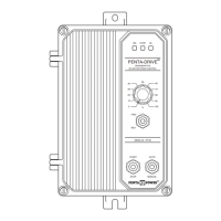
C. DC Tach-Generator Voltage Selection
(J3) – Jumper J3 is factory set to the
“A180” position for 180 Volt motors.
When connecting a tach-generator to
Terminal Block TB3, set Jumper J3 to the
corresponding voltage of the tach-gener-
ator being used. See Figure 19.
Note: If using a tach-generator other
than 7V or 50V per 1000 RPM, see
Section IIIK, on page 13.
D. Motor Current Selection (J4) – Jumper J4 is factory set to the “10A” position for 10 Amp
motors. For lower current motors, set Jumper J2 to the corresponding current of the
motor being used. See Figure 20 and Table 6.
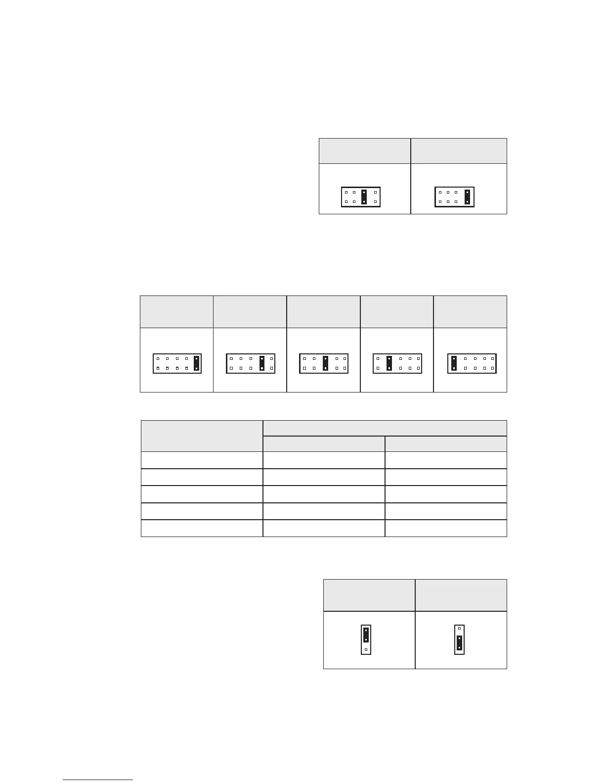
E. Analog Input Signal Voltage Selection
(J5) – Jumper J5 is factory set to the “15V”
position for use with a potentiometer to
control motor speed. To control motor
speed using a 0 - ±10 Volt DC isolated
analog signal voltage set Jumper J5 to the
“10V” position. To control motor speed
using a 0 - ±15 Volt DC
isolated analog
signal voltage, set Jumper J5 to the “15V”
position. See Figure 21.
Note: Connect the isolated signal voltage
to SIG (signal) and COM (-) terminals. If an isolated analog signal voltage is not avail-
able, install the optional Signal Isolator SIRC (P/N 8842).
J3 Set for 7V per 1000
RPM Tach-Generator
J5 Set for
0 – ±10 Volt Input Signal
J5 Set for
0 – ±15 Volt Input Signal
(Factory Setting)
J3 Set for 50V per 1000
RPM Tach-Generator
 Loading...