Copyright 2011 KE2 Therm Solutions, Washington, Missouri 63090
Bulletin N.1.1 August 2011 supersedes Bulletin N.1.1 July 2011 and all prior publications.
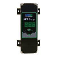
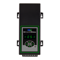
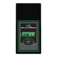
KE2 EvaporatorEfciency
Installation Instructions
thermsolutions
TM
Installation N.1.1 August 2011
Page 16
KE2 Therm Solutions, Inc.
209 Lange Drive. Washington, MO 63090
1-888-337-3358 . www.ke2therm.com
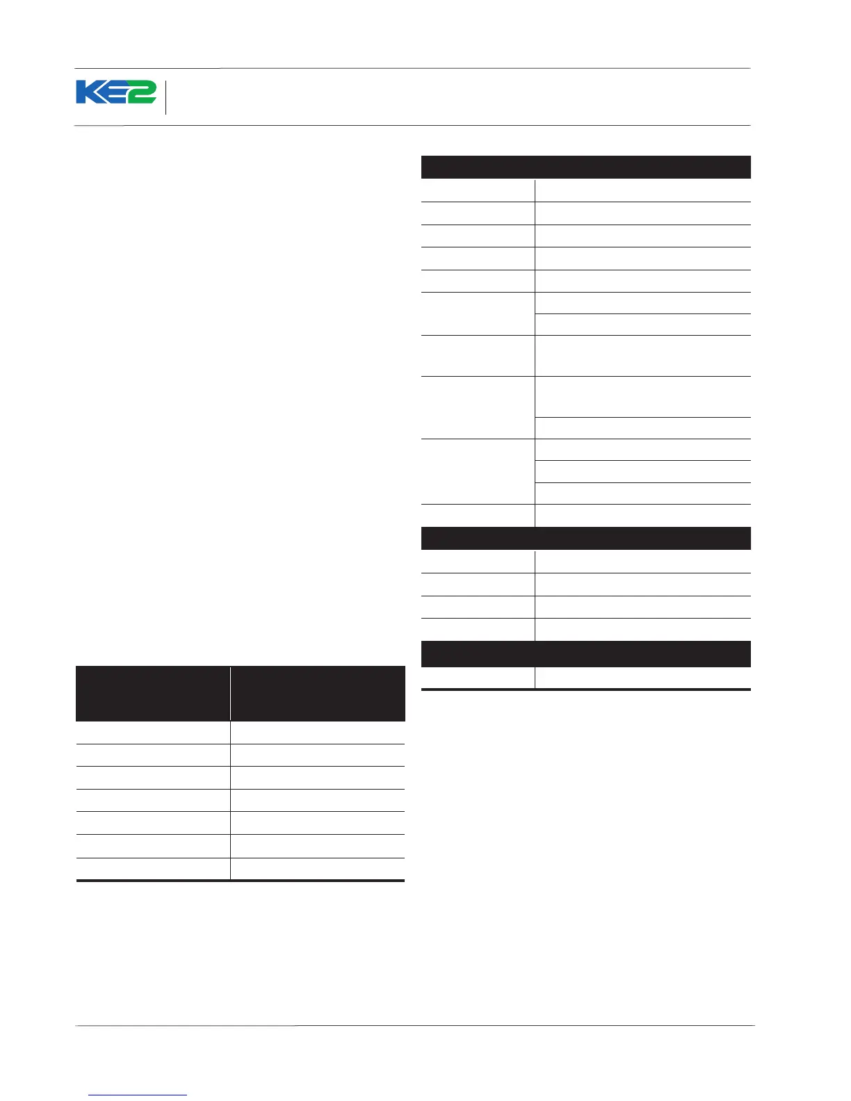
Table 6 - Specications
Controller
Input Voltage:
120V or 240V
Ambient Temp:
-40° to 140°F
Operating Temp:
-40° to 140°F
Display:
4 digit alphanumeric LED
IP Rating:
IP65
Inputs:
4 temperature sensors (KE2 SKU 20199)
1 pressure transducer (KE2 SKU 20201)
Valve Types:
unipolar and bipolar stepper motors (12V)
(Beacon II is 21V)
Relays:
20A resistive (defrost heater)
10A inductive (evaporator fan)
2–3A inductive rated cycles
Digital Inputs:
door switch (dry contact)
dual temp setting (dry contact)
loss of power
Communication:
Standard TCP/IP
Pressure Transducer
Pressure Range:
0 to 150 psia
Proof Pressure:
450 psi
Burst Pressure:
1500 psi
Operating Temp:
-40° to 275°F
Temperature Sensor
Sensor Specs:
-60° to 150°F moisture resistant package
Communication
The KE2 Evap uses standard TCP/IP communication. The con-
troller is equipped with an RJ-45 female connector to connect
to Ethernet cable.
To communicate with the controller, the user will use either a
computer with a web browser or the KE2 MasterView. The in-
formation is stored on the controller, so special software is not
required.
A standard Ethernet cable should be used between the periph-
eral device and the controller. One end is connected to the
controller, and the other to the Ethernet port on the PC or Mas-
terView. The Ethernet port will look similar to a telephone jack.
The dierence is the Ethernet port is larger with 8 wires instead
of 6.
In installations where multiple evaporators are piped to a single
condenser, networking the controllers is required. This prevents
damage to the system by synchronizing the defrost cycles. Net-
worked controllers have an additional safety layer to protect the
system. When networked, the controllers share information,
such as air temperature, to allow a controller in alarm mode to
continue to provide refrigeration until the system is serviced.
When networking multiple controllers an ethernet switch or
router is required. KE2 Network Router is available in a 4-port
and KE2 Switch in an 8-port model. The KE2 Router includes
wireless access. The 8-port switch should be used for larger
networks. Multiple switches can be ganged together to cre-
ate additional ports for the network. When necessary, the lo-
cal Network Adminstrator should be contacted to facilitate the
network installation.
Table 5 - Ethernet Specications Summary
Specications Ethernet -
Unshielded Twisted Pair
(UTP)
Topology
star
Network Friendly
YES
Maximum Cable Length
330 feet (copper)
Maximum Data Rate
1,000 mbs
Native Internet
YES
Supported Devices
thousands
Response Time
milliseconds
For additional information on Ethernet Cable, consult IEEE 802.
 Loading...