Copyright 2011 KE2 Therm Solutions, Washington, Missouri 63090
thermsolutions
TM
Installation N.1.1 August 2011
Page 7
KE2 EvaporatorEfciency
Installation Instructions
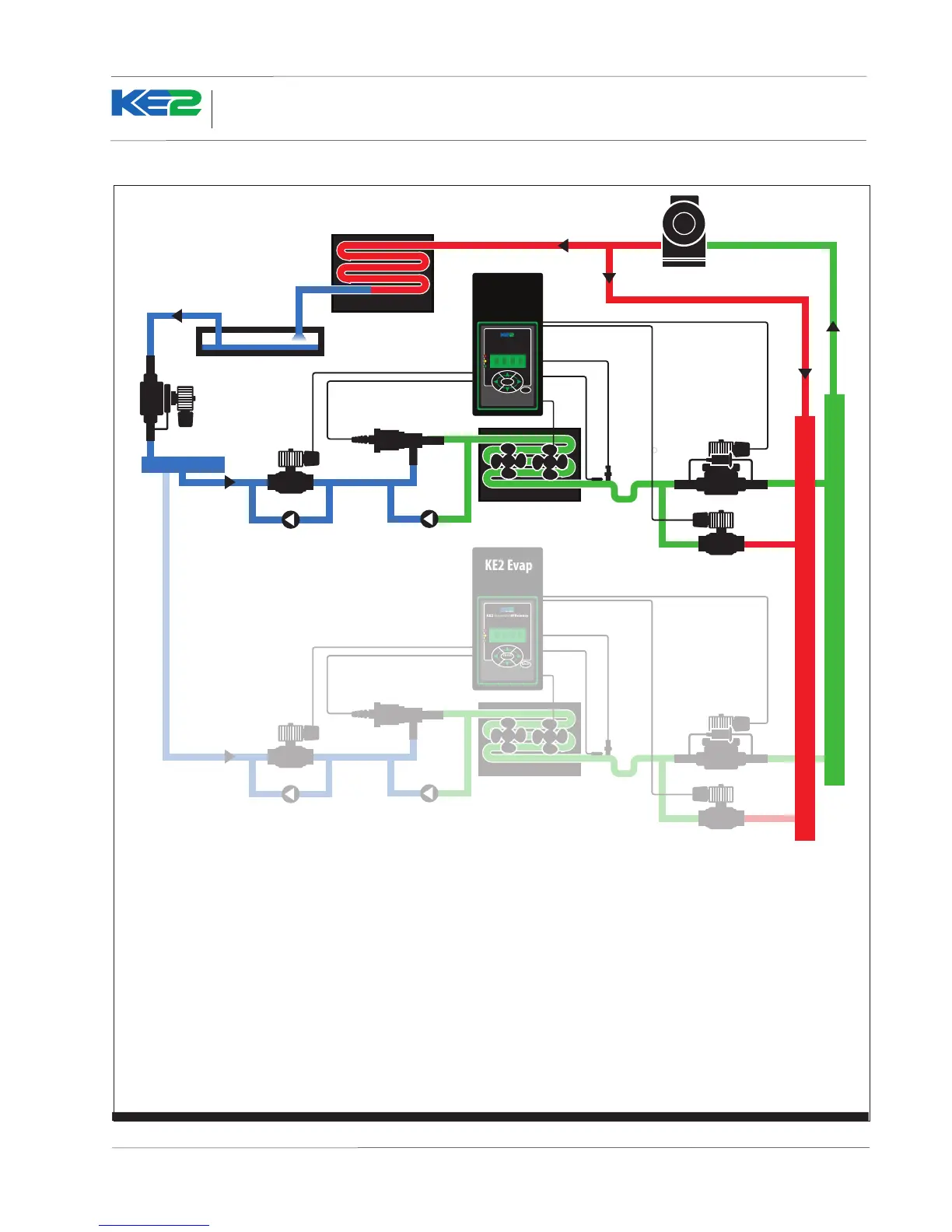
Figure 6 - Typical Piping Diagram - Hot Gas
KE2 EvaporatorEfficiency
TM
thermsolutions
ENTER
BACK
KE2 Evap
KE2 EvaporatorEfficiency
TM
thermsolutions
ENTER
BACK
Condenser
KE2 Evap
Compressor
Evaporator
Defrost Solenoid Valve
EPR with
Suction Stop
Check ValveCheck Valve
HSV
Electric Valve
Liquid Line Solenoid/Compressor Relay
Liquid Line
Solenoid Valve
Defrost Relay - NC
Pressure Transducer
Fan Relay
Temp. Sensor
Additional
circuits
Piping shown for illustration purposes only.
Suction Header
Defrost Header
Liquid Header
Liquid
Dierential
Valve
Receiver
Note: Controllers must be bonded and Multi Evaporator Defrost (MEVD) setpoint must be set to Independent (INDP)
Defrost Relay - N0
 Loading...