Copyright 2011 KE2 Therm Solutions, Washington, Missouri 63090
KE2 EvaporatorEfciency
Installation Instructions
thermsolutions
TM
Installation N.1.1 August 2011
Page 6
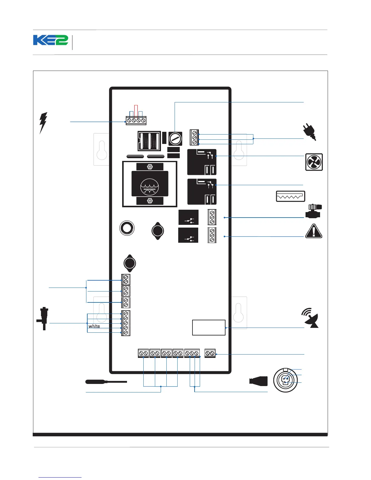
Figure 5 - KE2 Evaporator Eciency - Diagram (back view)
220
110
110
Temperature Sensors Pressure
Transducer
TSuctTAux TAirTCoil
line / L1
ground
neutral / L2
NC
NO
NO NC
NO NC
COM
COM
NC
Power In
green
red
black
NO
Transformer
3A Relay
3A Relay
COM
COM
COM
NC
NO
COM
NC
NO
18V
DI 1
DI 3
DI 2
Electric Valve
Temperature Sensors (4) Pressure Transducer
RJ45 Ethernet Connection
Not Used
Fuse
ground
red
green
white
black
Alarm Relay
Fan Relay
(10 amp)
-5
signal
+5
Defrost Heater Relay
(20 amp)
Bk/MDL-1/4
Time Delay
Liquid Line Solenoid
Power In
(compressor)
door switch
dual temp setting
pumpdown
Digital Inputs
Pressure Transducer
Wiring Detail
ground
supply
voltage
output
Voltage
Jumper
 Loading...