Q.1.3 July 2015
Page 7
KE2 EvaporatorEfciency
Quick Start Guide
© Copyright 2015 KE2 Therm Solutions, Inc., Washington, Missouri 63090
Study the existing wiring.
Determine the location of the fol-
lowing: incoming power, fan leads,
heater leads, defrost termination
leads, and fan delay leads.
15
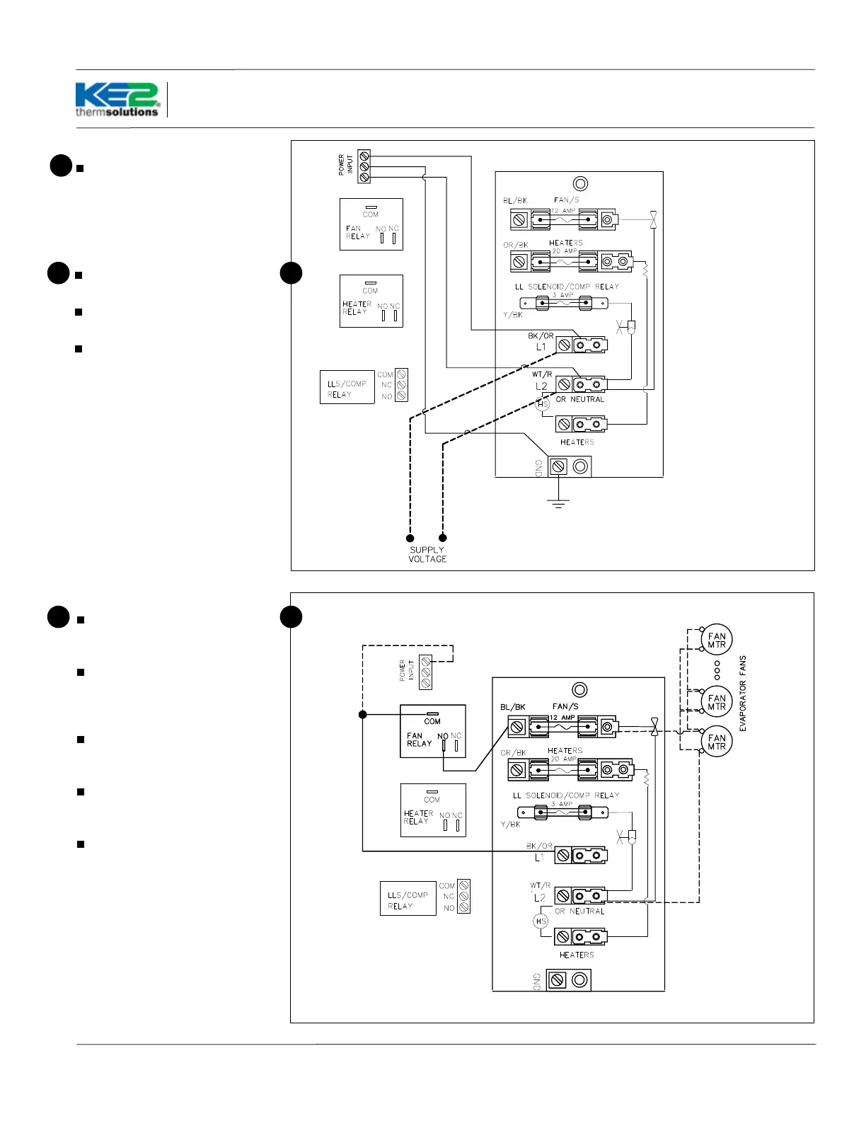
Evaporator wiring – Controller
Strip the end of the wires used to
power the controller.
Attach to the line power to provide
continuous power to the controller.
Attach ground wire.
Note: Ground is required for the inter-
nal safeties to operate properly.
16
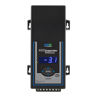
Evaporator wiring – Fans
Strip the ends of the wires (con-
nected to the KE2 Evap) used to con-
trol the evaporator fans.
The fan wires can be attached
to the terminal block using either
screw down terminals or spade
connectors.
Attach one of wires to the L1/Line.
This wire will be connected to COM
of fan relay on the controller.
Attach the wire connected to the
NO terminal on the Fan Relay to one
of the fan leads.
Connect L2/Neutral to remaining
fan lead.
17 17
16
KE2 Terminal Board
KE2 Terminal Board