29
GB
123 910
+
PE
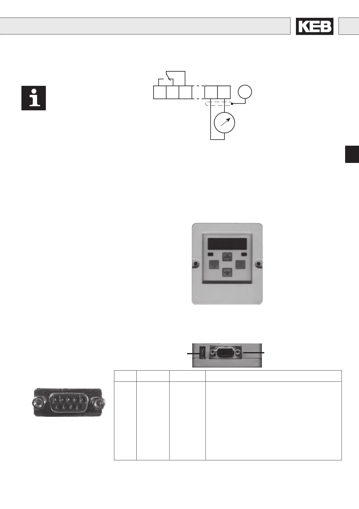
Analog output:
0...10VDC / max. 5mA
at Ri ≥ 56 KΩ const.
1.2.5Outputs
Installation and Connection
As an accessory to the local operation an operator is necessary. To
prevent malfunctions, the inverter must be brought into nOP status
before connecting/disconnecting the operator (open control release
terminal X1.19 C-Version/X1.14 S-Version). When starting the inverter
whitout an operator, it is started with the last stored values or factory
setting. The operator is obtainable in different versions:
2. Operation of the unit
Interface control
Transmit "LED flickers"
Double function keyboard
Operating-/Error display
Normal "LED on"
Error "LED blinks"
5-digit LED Display
2.1 Digital operator
Part-No. 00.F4.010-2009
9876
5 4 3 2 1
RS232/RS485
PIN RS485 Signal Meaning
1 – – reserved
2 – TxD Transmitter signal/RS232
3 – RxD Receiver signal/RS232
4 A' RxD-A Receiver signal A/RS485
5 B' RxD-B Receiver signal B/RS485
6 – VP Voltage supply-Plus +5V (I
max
= 10 mA))
7 C/C' DGND Data reference potential
8 A TxD-A Transmitter signal A/RS485
9 B TxD-B Transmitter signal B/RS485
PE-Connection
2.1.1 Interface operator
Part-No. 00.F4.010-1009
In the Interface operator there is an additionally isolated RS232/RS485-
Interface integrated.
Informations about other versions of operators contact KEB!
Relay output:
30V DC / 0,01...1A
When using inductive
consumers at the relay output
a protective wiring (i.e. free
wheeling diode) is necessary
to protect the relay!
Artisan Technology Group - Quality Instrumentation ... Guaranteed | (888) 88-SOURCE | www.artisantg.com
 Loading...


