Pn - Parameter
36
This function protects the inverter from switching off caused by overcurrent, during
constant speed. Depending on the torque/speed characteristic of the connected
machine, a load reduction is reached by deceleration (e.g. fan) and/or acceleration
(e.g. drilling machine). The following modes can be set by Pn.12.:
Value Mode
0 Function deactivated
1 Decelerate onto oP. 4
2 Accelerate onto oP. 5
3 Decelerate onto uF. 9
4 Accelerate onto oP. 8
In Pn.13 the comparison value for the function is set. Pn.13 is compared with the
actual rate of utilization. If this is larger than Pn.13 the output frequency is changed,
dependent on the set mode with the given ramp time by Pn.14.
When the current limit is exceeded the inverter decelerates/accelerates with the set
ramp times in oP.11/oP.12 onto the original setpoint.
The function is deactivated at setpoint changes (e.g. setpoint jumps > 0.5 Hz, reverse)
and at start (acceleration out LS).
Stall Mode (Pn.12)
Stall Level (Pn.13)
Stall ACC/DEC
Time (Pn.14)
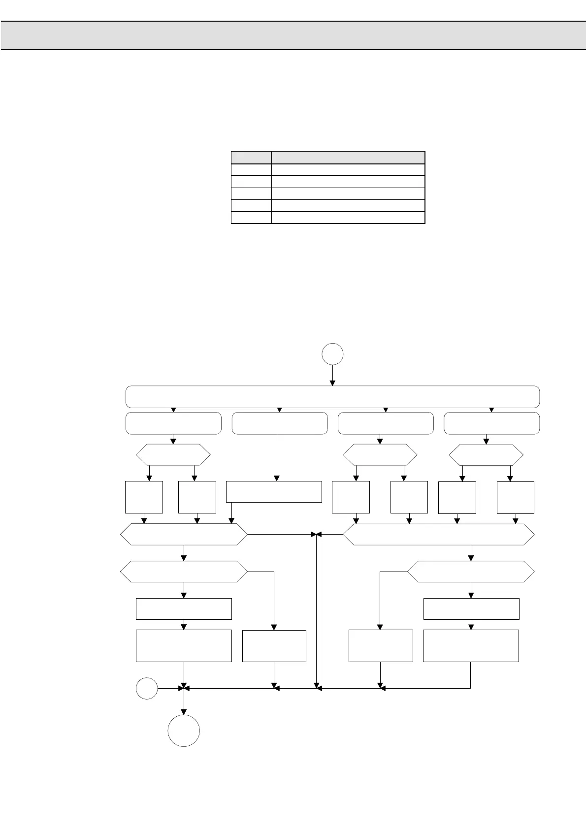
Stall Mode
Flow Chart
Part 2
no
no
yes
no
no
yes
yes
yes
no yes no yes
no yes
B
A
op. 9 = off ?
39
Setpoint =
- op. 8
41
Setpoint =
- op. 9
40
op. 7 = off ?
35
Setpoint =
- op. 5
37
Setpoint =
- op. 7
36
op. 6 = off ?
29
Setpoint =
- op. 4
31
Inverter - Status =
LAS
51
Actual value is limited
on setpoint
50
Actual value - stall step
49
LA-stop active ?
48
Setpoint reached?
47
Inverter - Status =
LdS
46
Actual value is limited
on setpoint
45
Actual value + stall step
44
LD-stop active ?
43
Setpoint reached?
42
Case Stall-Mode
27
Stall-Mode = 4
38
Stall-Mode = 2
34
Stall-Mode = 3
32
Stall-Mode = 1
28
Setpoint = - uf. 9
33
Setpoint =
- op. 6
30
Check
uf. 9
52

 Loading...

