Installation and Connection
9
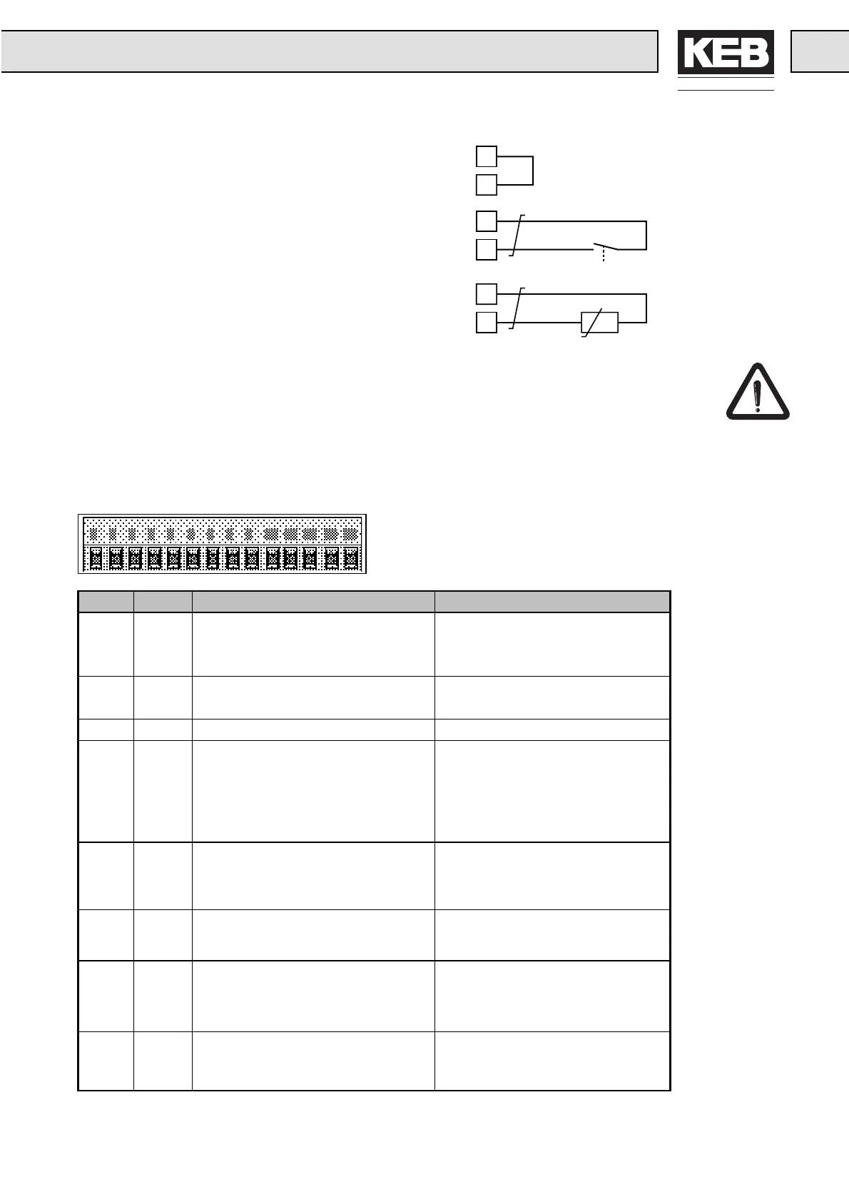
2.4.4 Temperature Monitoring
Bridge, when no monitoring occurs.
Thermocontact (NC-contact)
Temperature detector (PTC)
2.5 Connection and Control
To prevent maloperations caused by interference voltage supply observe the following:
•
Use shielded / drilled lines.
•
Install shield on one side of the inverter onto the earth potential.
•
Install control and power cable separately (distance about 10-20cm).
•
Install crossing, if not avoidable, in a right angle.
2.5.1 Terminal
Terminal X1
Pin Name Function Default Function
X1.1 RLA
ro
rammable rela
out
ut
X1.2 RLB A = NO-contact / B = NC-contact / alarm relay
X1.3 RLC C = Basis (Out2)
X1.4 I1
ro
rammable di
ital in
uts fixed fre
uenc
1
X1.5 I2 fixed frequency 2
X1.6 0V
round
round for di
ital I/Os
X1.7 CRF 10 V output supply voltage for setpoint
potentiometer
X1.8 REF setpoint input 0...10VDC for analog setpoint input
X1.9 COM common ground for analog I/O’s
X1.10 AN-
OUT
analog output
(digital output)
(Out1)
analog output e.g.:
the output frequency (An.14 = 0)
or digital output (An.14 = 7)
X1.11 Uext 15 V supply voltage for digital I/O’s
X1.12 REV direction of rotation: reverse direction of rotation
X1.13 FOR forward presetting: forward has priority
X1.14 ST control release / reset power modules released; reset
when opened
OH
OH
OH
OH
OH
OH

 Loading...

