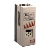
Do you have a question about the KEB COMBIVERT F4-S and is the answer not in the manual?
Explains the meaning of pictographs like Danger, Warning, and Caution.
Highlights need for qualified personnel and capacitor discharge warnings.
Details terminal assignments for Control circuit Version C.
Lists pin functions and descriptions for Terminal Strip X1.
Guidelines for connecting control inputs to prevent interference.
Wiring diagrams for digital inputs with internal/external voltage supply.
Connecting analog inputs and preventing set value fluctuations.
Notes on relay output wiring and protective measures.
Details terminal assignments for Control circuit Version S.
Lists pin functions and descriptions for Terminal Strip X1.
EMC guidelines for control and power cable connections.
Wiring diagrams for digital inputs (internal/external supply).
Analog input set-point configurations.
Notes on relay output wiring and protective measures.
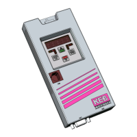
Explains the digital operator and its different versions.
Details on the RS232/RS485 interface operator.
Explanation of keyboard functions and parameter entry.
Comprehensive list of parameters, ranges, and settings.
Instructions for barring and releasing CP parameters with passwords.
Explains status displays like frequency, load, and inverter status.
Details on setting rated frequency, boost, and acceleration time.
Setting the minimum operating frequency.
Setting the maximum operating frequency.
Configuring three fixed frequencies selectable via inputs.
Parameters for optimizing drive performance like ramp current.
Function for matching motor speed during deceleration.
Adjusting output voltage based on input voltage variations.
Balances speed changes caused by load variations.
Compensates for voltage drop during high load torques.
Parameter to determine how DC-braking is triggered.
Evaluates braking time based on CP.20 and frequency.
Adjusts the function of the output terminal based on various events.
Sets the switching point for the relay output.
Manual operation of the drive via keyboard controls.
How to change the motor's direction of rotation.
Setting or changing the desired speed value.
Procedure to exit the drive mode and return to parameter view.
Describes causes and display for undervoltage errors.
Describes causes and display for overvoltage errors.
Describes causes and display for overcurrent errors.
Describes causes and display for overload errors.
Indicates completion of cooling down after an overload.
Describes causes and display for overheat errors.
Describes causes and display for external overheat errors.
Indicates internal/external excess-temperature errors can be reset.
Describes causes for current limit resistor errors.
Procedure to set CP-parameters to read-only mode.
Procedure to set CP-parameters to read/write mode.
Procedure to activate drive mode using password.
| Brand | KEB |
|---|---|
| Model | COMBIVERT F4-S |
| Category | Control Unit |
| Language | English |


 Loading...