3.3.7 DC link / braking transistor function
Unit size 12 13 14
DC link rated voltage @ U
N = 400 V UN_dc / V 565
DC link rated voltage @ U
N = 480 V UN_dc_UL / V 672
DC link voltage working voltage range U
in_dc / V 260...750 ±0
DC switch-off level „Error! Underpotential“ U
UP_dc / V 240
DC switch-off level „Error! Overpotential“ U
OP_dc / V 840
Rated current DC
@ Uin_dc = 565 V Iin_dc / A 16 20 26
Rated current DC @ U
in_dc = 680 V Iin_dc_UL / A 13 19 22
Rated current DC
@ Uout_dc = 565 V Iout_max_dc / A 16 20 26
Rated current DC
@ Uout_dc = 680 V Iout_max_dc_UL / A 13 19 22
DC switching level braking resistor
1)
UB_dc / V 780
Max. braking current I
Bmax / A 28 34 34
Min. brake resistance value R
Bmin /Ω 33 25 25
DC link capacity C / uF 470 560 680
Protection function for braking transistor (GTR7)
2)
—
Table 20: DC link / braking transistor function of the 400 V units
1)
The DC switching level for the braking transistor is adjustable. The default value is the value spec-
ied in the table.
2)
No protective function, => “Wiring of an intrinsically safe braking resistor”.
NOTICE
Destruction of the drive converter if the value has fallen below the
minimum brake resistance value
► The minimum brake resistance value must not fall below!
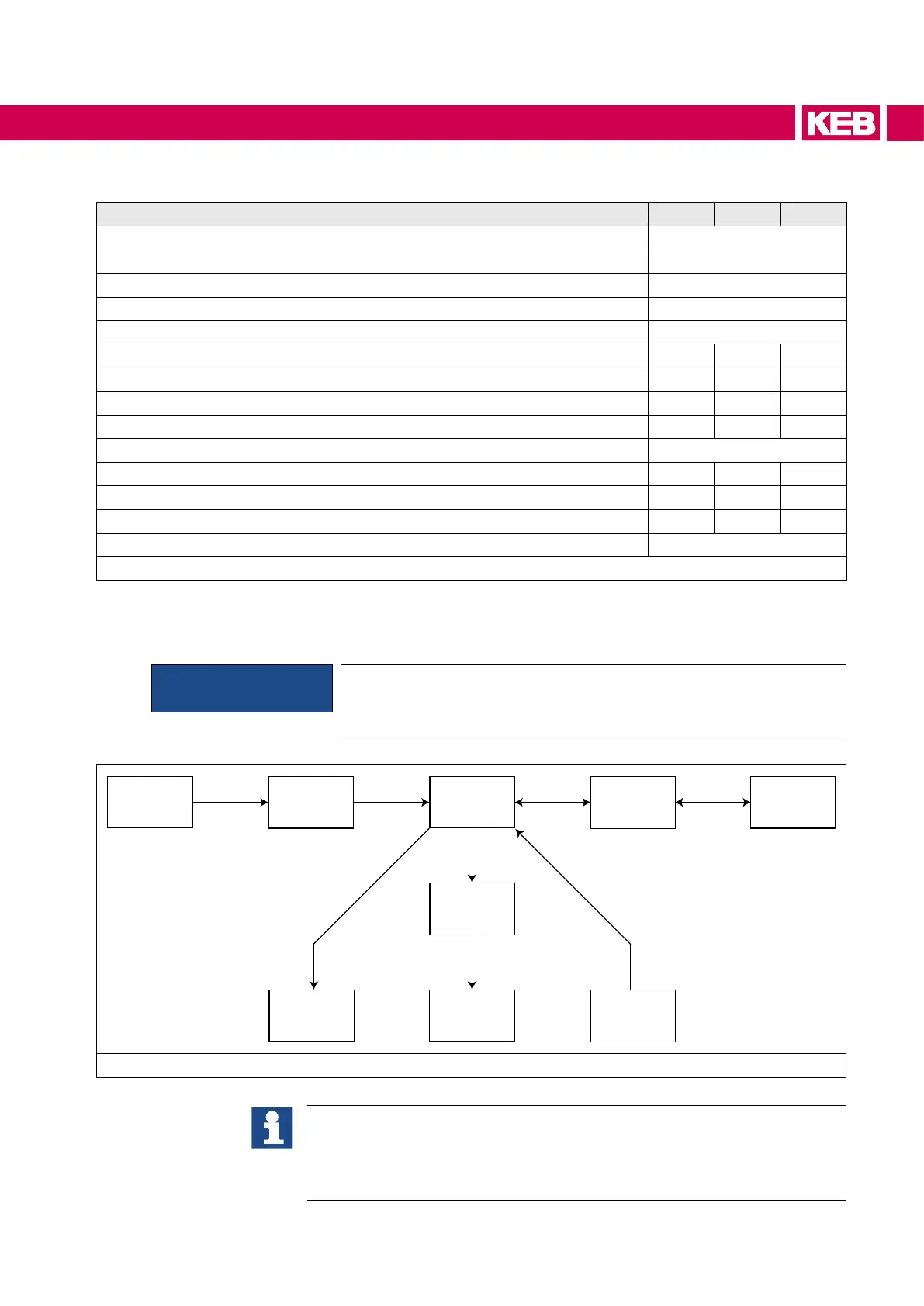
Net
Rectier
DC link
Inverter
Braking
transistor
(GTR7)
Motor
DC Out
Braking
resistor
DC in
I
in IN
Iout_dc IB
Iin_dc
Figure 7: Block diagram of the energy ow
Activation of the braking transistor function
The function must be activated with parameter "is30 braking transistor func-
tion" in order to use the braking transistor (GTR7).
Further information can be found in the download area of www.keb.de under
the search term „S6 Programming Manual“.
37
UNIT DATA