6.21 Operation 6.21
Using the Cutting blade
Changing the Cutting blade
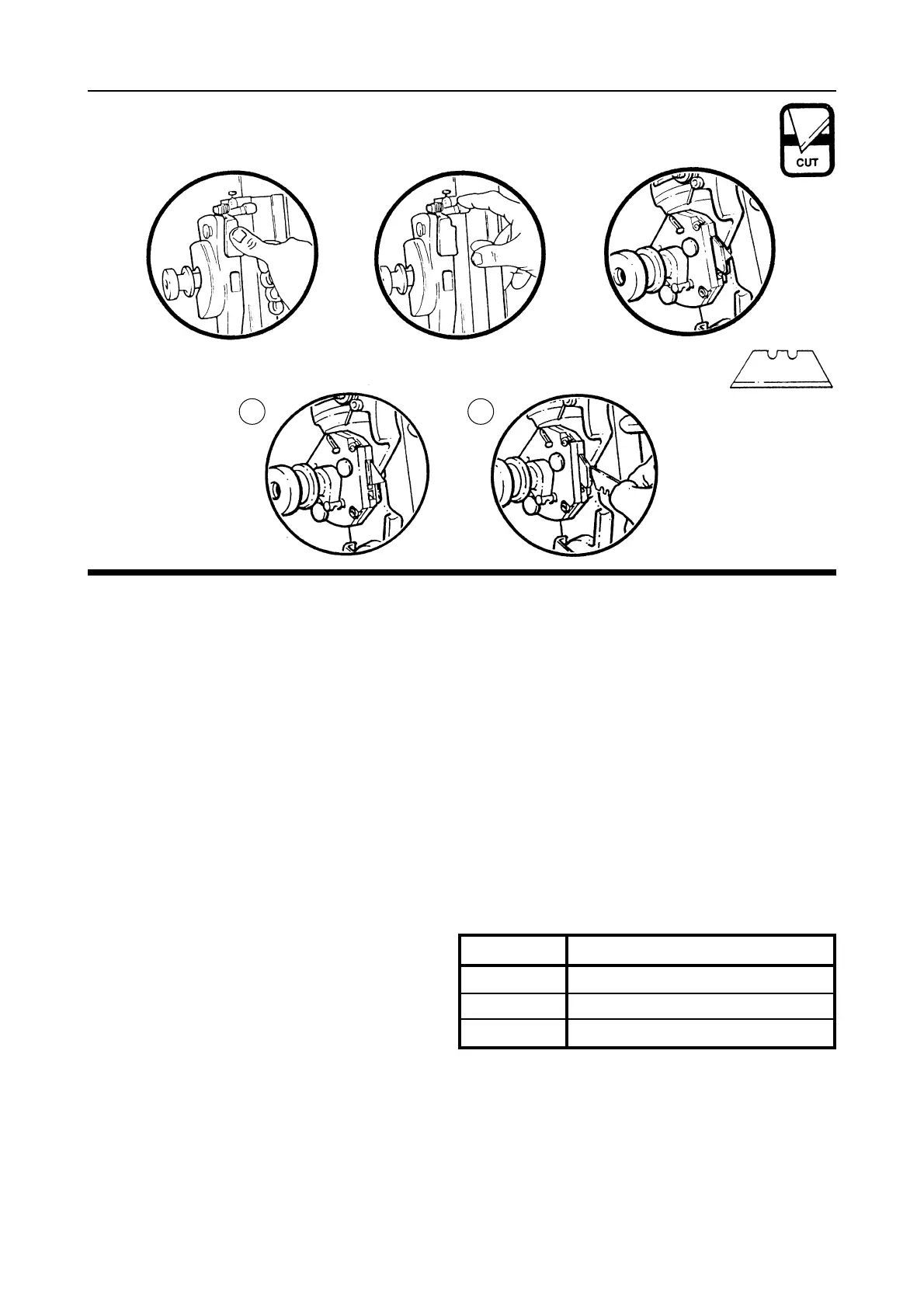
Basic Cutting Technique Select the Cutting Blade position on the turret and clamp the material in the machine.
Move the cutting head beyond the top of the material to be cut.
1. Press to engage the cutter.
Draw the cutter down to the bottom of the machine where it will disengage automatically.
2. Should you engage the cutter by mistake or for any reason want to disengage the cutter without
moving it to the bottom of the machine pull down the cutter release lever.
Using the blade support plates The two support plates either side of the blade are designed to give
maximum rigidity of the blade when cutting hard or dense materials.
To adjust the support plates swing down the cutter guard by undoing the guard locking knob.
3. Turn the turret
1
/
2 turn until blade is pointing towards you, unlock the blade clamping screw, the
support plates can be adjusted by sliding the black pin in the slot. Move the plates to suit
the material.
For cutting most materials the support plates can be set about 12mm (
1
/2”) from the blade tip.
Ratchet Latch
5. A unique feature of the Excalibur is the ‘Ratchet Latch’, this enables thick dense materials (such
as PVC foam board) to be cut easily in stages. Count the number of ‘clicks’ to position the blade just below
the surface of the material to make your first cut then add an extra ‘click’ for the second and subsequent cuts.
6. Pull down the Latch Lever to disengage the
ratchet if required.
As a rough guide when cutting PVC foam boards:-
The blades are ‘Medium Duty Utility Blades’ as shown.
Changing the cutting blade
1a. Unlock and swing down the cutter guard, rotate the turret so the cutting blade is facing outwards.
Release the blade clamping screw.
Push the black pin away from you as far as it will go.
2a. Change or turn over the blade and replace it between the two clamping plates, push the blade in as far as it
will go.
Set the Clamp plates in position. Whilst holding the blade in position, tighten the blade clamping screw and
rotate the turret back to the cutting position. Replace the guard ensuring it is locked closed.
THICKNESS TAKE
3mm (1/8”) Initial surface cut + 1 additional cut
5mm (1/4”) Initial surface cut + 1 or 2 additional cuts
10mm (3/8”) Initial surface cut + 3 or 4 additional cuts
1a 2a
➠
➠
➠
➠
➠
 Loading...