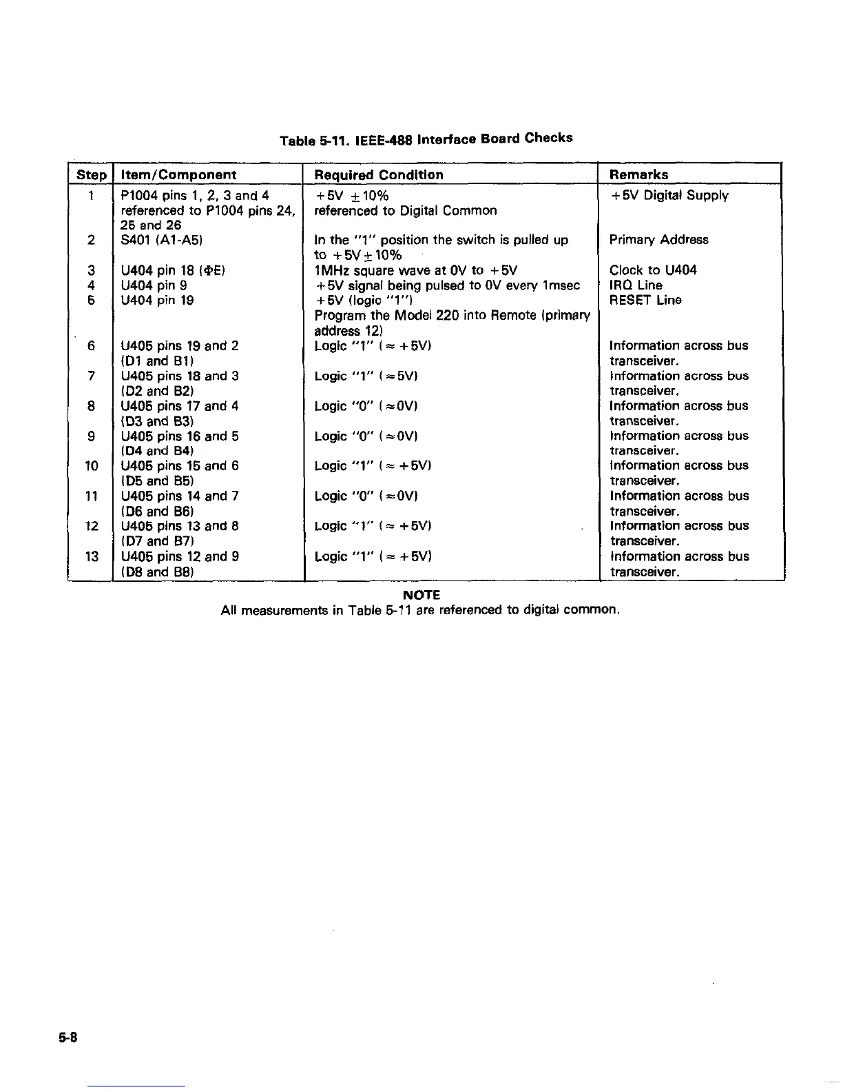
Table 6-11. IEEE-488 Interface Board Checks
Step Item/Component Required Condition
Remarks
1 P1004 pins 1. 2, 3 and 4
+5v *lO% + 5V Digital Supply
referenced to P1004 pins 24, referenced to Digital Common
25 and 26
2 5401 (Al-A51
In the “1” position the switch is pulled up Primary Address
to +5v+lo%
3 U404 pin 18 l@Ei 1MHz square wave at OV to +5V Clock to U404
4 U404 pin 9 + 5V signal being pulsed to OV every I msec IRQ Line
5 U404 pin 19 +5V (logic “1”)
RESET Line
Program the Model 220 into Remote (primary
address 12)
6 U405 pins 19 and 2 Logic “1” l ii + 5VI Information across bus
lD1 and Bll transceiver.
7
U405 pins 18 and 3
Logic “1” l15Vl
Information across bus
lD2 and 82)
transceiver.
8 U405 pins 17 and 4
Logic “0” l I OVl Information across bus
lD3 and 83)
transceiver.
9 U405 pins 16 and 5
Logic “0” l =OVl Information across bus
ID4 and B4l
transceiver.
10 U405 pins 15 and 6
Logic “1” l 5 + 5Vl
Information across bus
lD5 and 65) transceiver.
11 U405 pins 14 and 7
Logic “0” i =OVi
Information across bus
lD6 and 66)
transceiver.
12 U405 pins 13 and 8
Logic “1” l = + 5Vi
Information across bus
lD7 and 87) transceiver.
13
U405 pins 12 end 9
Logic “1” i = + 5Vl
Information across bus
(DE and 881
transceiver.
NOTE
All measurements in Table 5-l 1 are referenced to digital common.
6-E