Switching module connections
Connections for the switching module are shown below. As shown, each of the 40 channels can be
used to perform 2-wire resistance measurements.
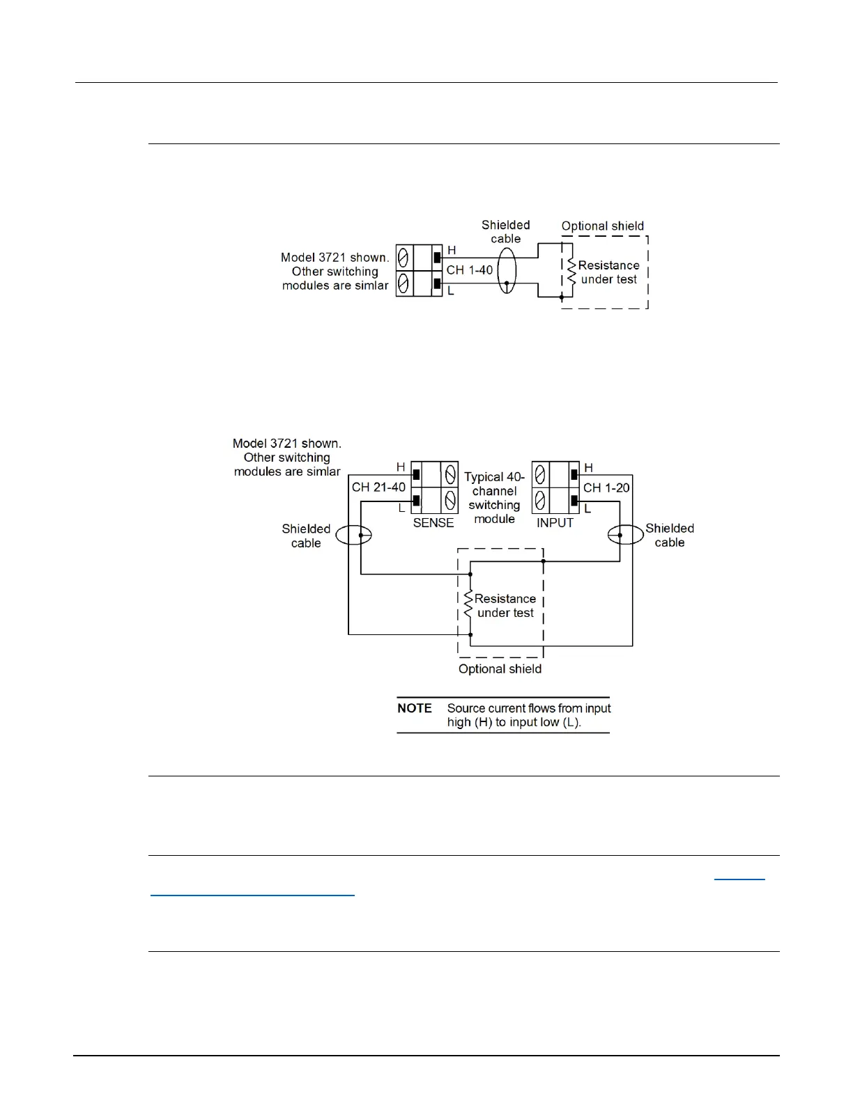
Figure 51: Two-wire switching module resistance connection
For 4-wire resistance measurements, a channel pair is used for each 4-wire measurement, as shown
below. For 4-wire resistance connections on a 40-channel switching module, channels 1 through 20
(which are used as the INPUT terminals) are paired to channels 21 through 40 (which are used as the
SENSE terminals). Channel 1 is paired to channel 21, channel 2 is paired to channel 22, and so on.
Figure 52: Four-wire switching module resistance connection
Cable leakage
For high resistance measurements in a high humidity environment, use Teflon
TM
insulated cables to
minimize errors due to cable leakage.
Shielding
To achieve a stable reading, it helps to shield resistances greater than 100 kΩ. As shown in Analog
backplane connector (rear panel) (on page 4-18), place the resistance in a shielded enclosure and
connect the shield to the INPUT LO terminal of the instrument electrically.
Commonside ohms
The following figure provides a switching schematic for the 3721 when measuring 4-wire commonside
ohms.
 Loading...


