Series 3700A System Switch/Multimeter Reference Manual Section 2: Installation
3700AS-901-01 Rev. D/June 2018 2-29
Port configuration
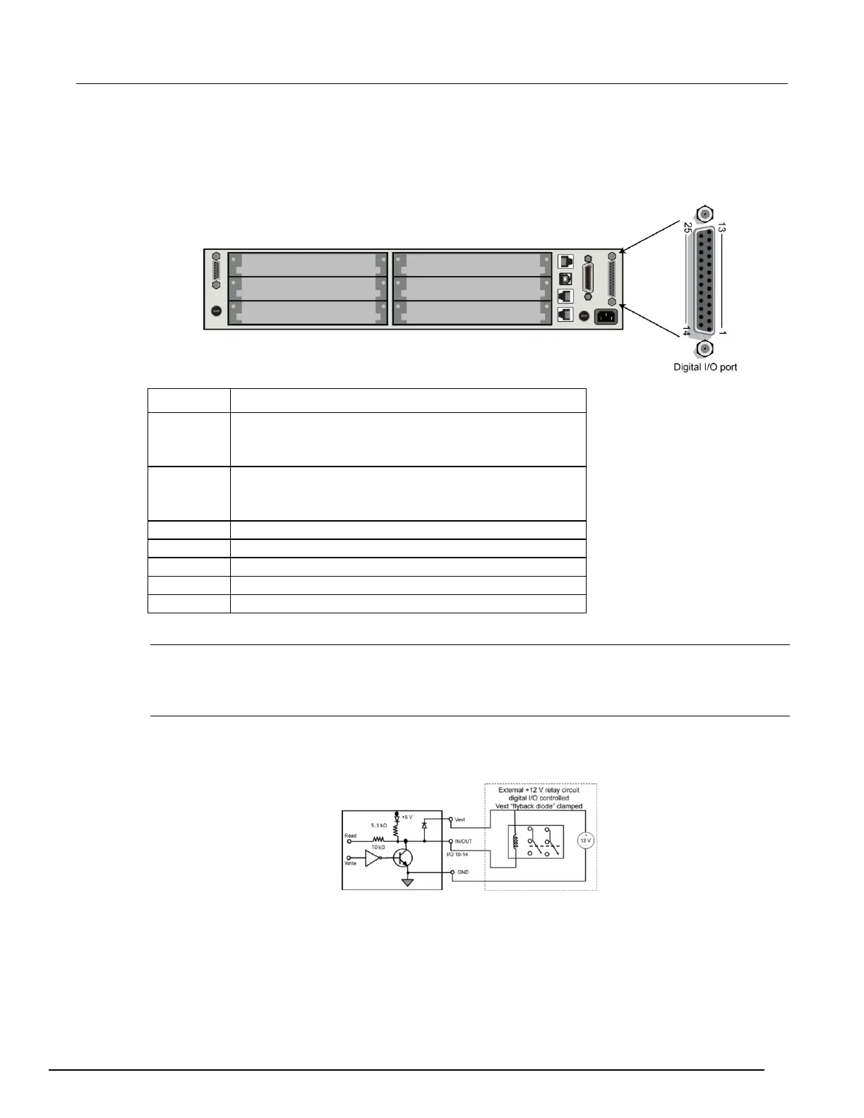
The digital I/O port, a standard female DB-25 connector (shown below), is on the rear panel.
Figure 15: Digital I/O port
Digital I/O #1
...
Digital I/O #9
Digital I/O #10 (high-current pins)
...
Digital I/O #14
Pin reserved for future use
Connecting cables
Use a cable equipped with a standard male DB-25 connector (Keithley Instruments part number
CA-126-1).
Vext
The Series 3700A digital I/O provides flyback diode pins named Vext. When connected, Vext can
clamp external inductive circuitry (for example, relay drive coils) from +5 V to +33 V. Refer to the
figure below for a simplified digital I/O schematic.
Figure 16: Vext flyback
diode digital I/O
schematic
 Loading...


