Series 3700A System Switch/Multimeter Reference Manual Appendix B: Verification and adjustment
3700AS-901-01 Rev. D/June 2018 B-13
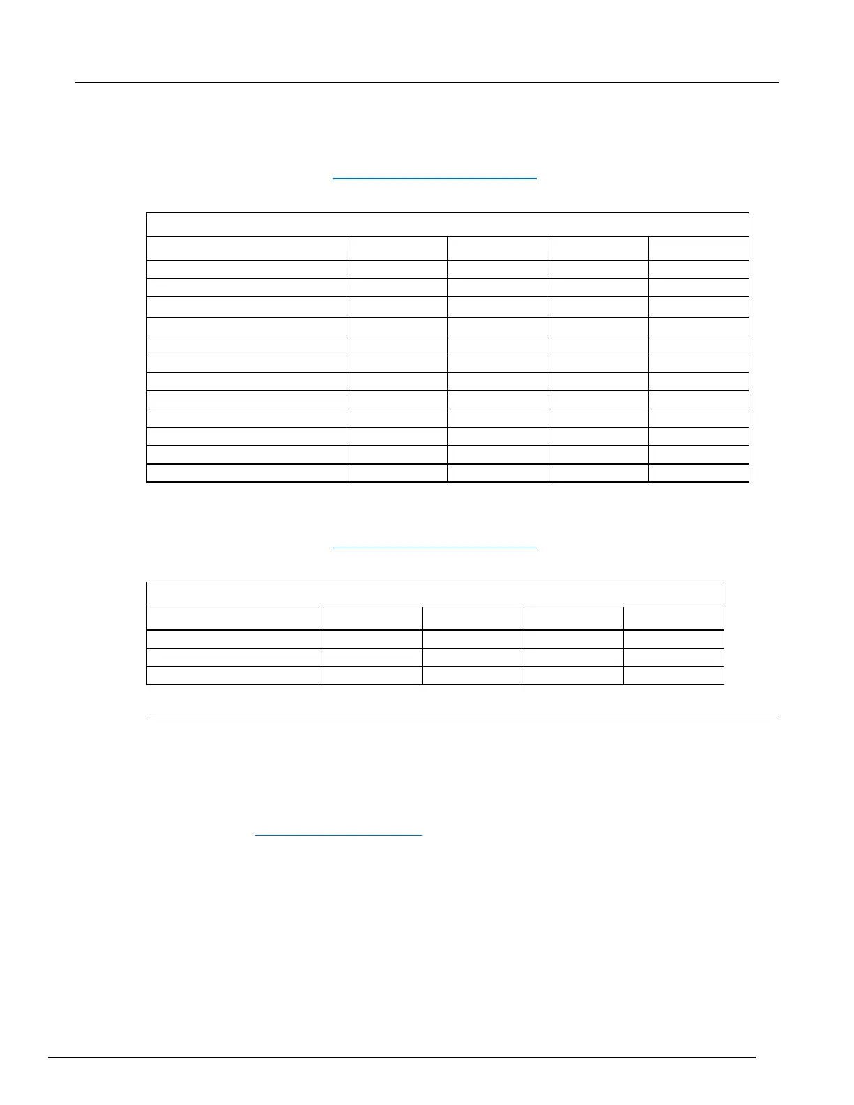
AC current verification data 1 mA to 1 A ranges
Use the following values to verify the performance of the Series 3700A. Actual values depend on
published specifications (see Example reading limit calculation (on page B-3)).
Connect to the Fluke 5700A calibrator
Verify AC Curr 1 mA at 20 Hz
Verify AC Curr 1 mA at 1 kHz
Verify AC Curr 1 mA at 5 kHz
Verify AC Curr 10 mA at 40 Hz
Verify AC Curr 10 mA at 1 kHz
Verify AC Curr 10 mA at 5 kHz
Verify AC Curr 100 mA at 40 Hz
Verify AC Curr 100 mA at 1 kHz
Verify AC Curr 100 mA at 5 kHz
Verify AC Curr 1 A at 40 Hz
Verify AC Curr 1 A at 1 kHz
Verify AC Curr 1 A at 5 kHz
AC current verification data 3 A range
Use the following values to verify the performance of the Series 3700A. Actual values depend on
published specifications (see Example reading limit calculation (on page B-3)).
Connect to the Fluke 5725A amplifier
Verify AC Curr 3 A at 40 Hz
Verify AC Curr 3 A at 1 kHz
Verify AC Curr 3 A at 5 kHz
Verifying frequency
To verify the Series 3700A frequency function:
1. Connect the Keysight 33220A function generator to the Series 3700A INPUT pins.
2. Set the function generator to output a 1 kHz, 5 V
RMS
sine wave.
3. Select the Series 3700A frequency function by pressing the FREQ key.
4. Verify that each Series 3700A frequency reading is within the limits contained in the table
contained in Frequency verification data (on page B-14).
 Loading...


