Kelly KHS High Voltage Sinusoidal Brushless Permanent Magnet Motor Controller User’s Manual V 1.25
3.2 Connections
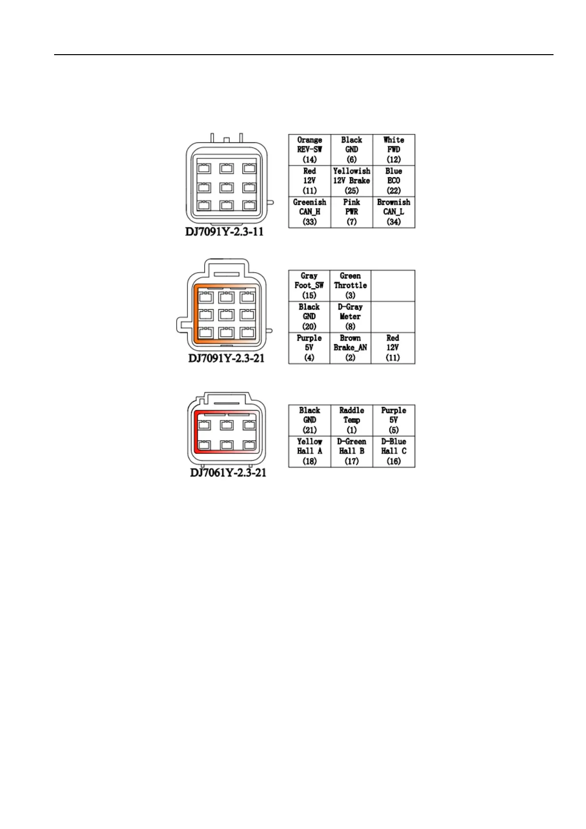
3.2.1 Pin definition of the Controller
1,The switch signal is valid to 12V on pin11.
2,12V capacity is low. This 12V only can be used for LED or switch signals,with a total current
not exceeding 20mA.
3,Boost and Brake analog regeneration mode used the same pin as pin2.
When Boost is disabled in the user program, the pin2 can be used as brake variable regen
mode. When Boost is enabled, the brake analog regen mode is inactivated automatically. Both
Boost and Brake variable regen mode can not be used at the same time.
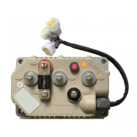
Figure 3:
Waterproof Connector
DJ7091Y-2.3-11 Pin Definition
(14) REV_SW: Reverse switch input. Orange
(6) RTN: Signal return or power supply return. Black
(12) FWD: Forward switch or High speed switch White
(11) 12V:12V Source
. Red
(25) 12V brake switch
. Yellowish
 Loading...