13. ELECTRICAL INSTALLATION
If residual current or earth leakage protection devices are to be used in the supply, appropriate sensitivity levels should be
used. Up to 300 mA trip level may be required to avoid nuisance tripping, particularly with inverters. If greater protection is
required then this can be provided for individual circuits.
Electrical connection is to individual motor terminal boxes, or a unit terminal box or control panel., Wiring instructions are
provided within this document. Generally `cage clamp’ type terminals are used. Pushing a correctly sized screwdriver into
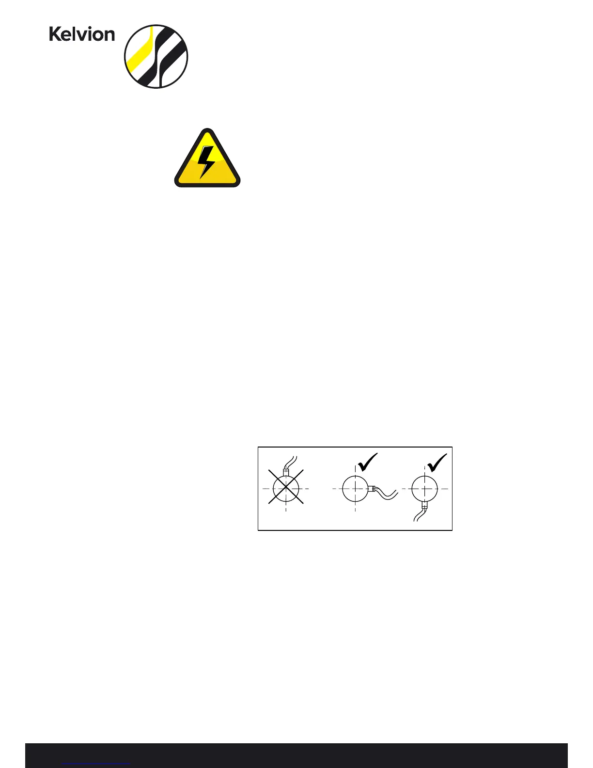
the square aperture adjacent to the conductor entry opens the terminal. It is the installer’s responsibility to ensure cable
entry is fit for purpose and that where appropriate cable support is applied. Care should be taken to ensure the box IP rating
is not compromised by the electrical supply cable entry.
Conductors between 1 and 2.5mm² are accommodated. Where wiring is to a motors individual terminal box the facility for
additional casework earth points are provided. When motor wiring is routed within the unit side covers, earth studs are pro-
vided under these covers for additional earth points on the casework. All AC single-phase motors have automatic internal
overload protection, and can be used in conjunction with a high quality `triac’ type speed controller. Some three phase AC
motors are also fitted with internal thermostats, wired back to their terminal blocks (TK). Check that the fan rotation of 3 phase
units is correct.
Reversing any two phases of the 3 phase AC motor supply can change the rotation. Reversing two phases of the EC motors
won’t change the rotation. In optional AC fan Contactor boxes the fan contactors are energised through these auto-reset,
normally closed, thermo¬stats. When internal thermostats are not used three phase motors MUST be protected against
overload and single phasing. Overloads must be set to cut out at FLC + 10% (FLC + 15% at -30°C) Failure to comply will render
motor warranties void.
Kelvion would recommend as general rule that each cable or group of cables will be supported at no greater than 500mm
intervals; but if national legislation recommends otherwise this should be followed. Cable size is determined by the motor
current, with the necessary duration for unit operating temperature. High Temperature cable is used where necessary. It is
the responsibility of the installation contractor to ensure the complete installation is appropriately electrically tested accord-
ing to national legislation.
Terminated Units
If no isolator is on the unit it is the installers’ responsibly to ensure appropriate isolation is incorporated within the system.
With or without unit isolation; it is the installers’ responsibility to provide over and short circuit protection for the installation.
Controls
Control options are supplied according to customer specification. Individual instructions are provided to guide the setting
and use of control options. When a control option is specified, the unit will contain the necessary equipment to isolate and
provide over current and short circuit protection for the unit.
Wiring Diagrams and Documentation
Wiring diagrams and other relevant documentation will either be supplied in the units’ junction box or in this document
ELECTRICAL VOLTAGE: Ensure that
1. The power supply is isolated before any installation or maintenance work is carried out.
2. The voltage, working fluid and the maximum working pressure stated on the product name-
plate is suitable for the working environment.