TECHNICAL SERVICE MANUAL FOR KEMPOWELD
APPENDIX 1. TROUBLESHOOTING FOR PCBs
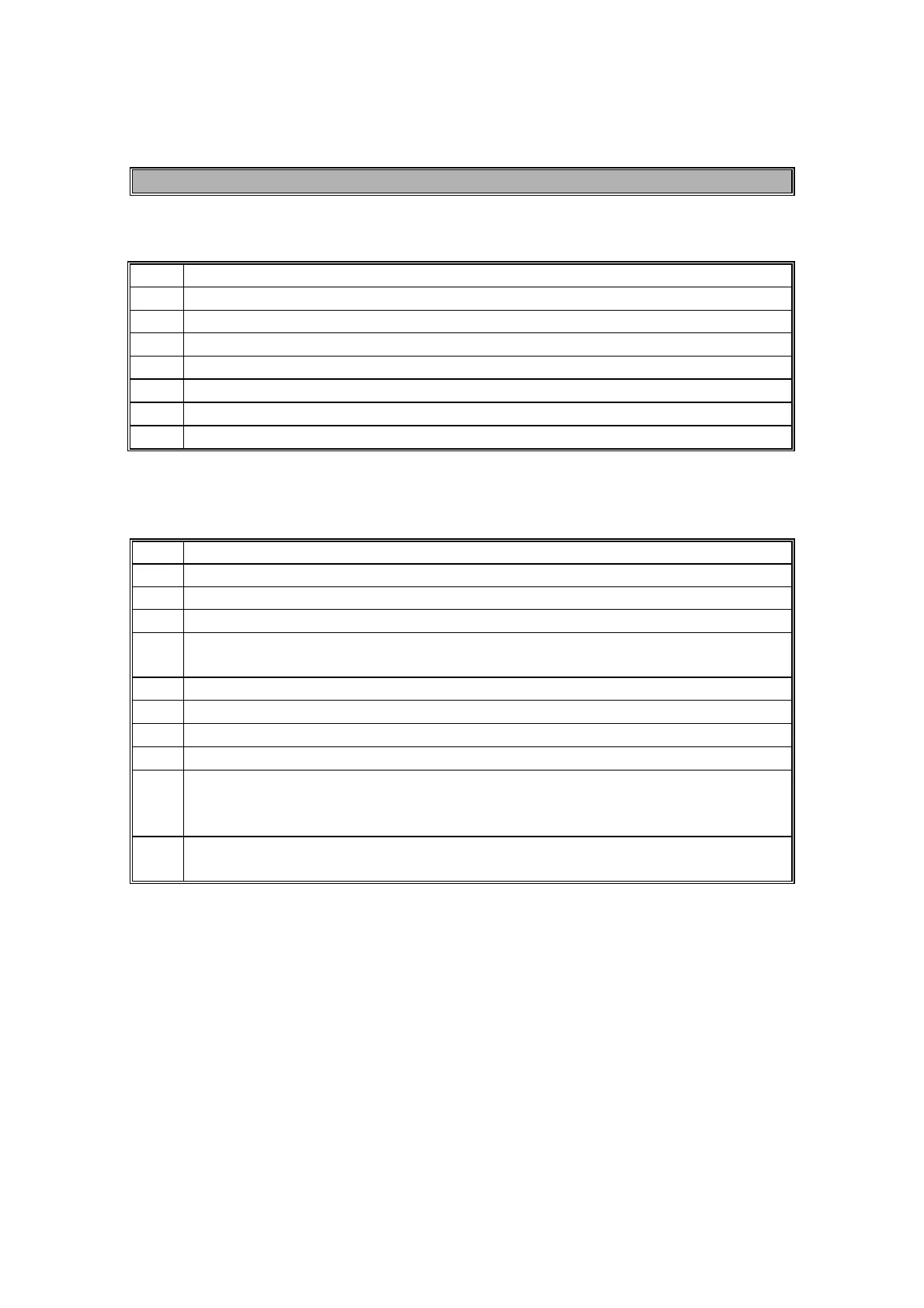
A001 POWER SOURCE
1. + 24 V over the capacitor C9
2.
+ 24 V over the capacitor C7 (FAN POWER SUPPLY)
3. + 15 V over the over the diode V2
4.
+ 12 V over the capacitor C10 (MSD
POWER SUPPLY)
5.
START => pin X2/11 to GND, 0V = start active
6.
START => V4 to GND, 0V = start active
7.
TP 4 = 15 V, FAN ON CONTROL
8.
FAN TIMER voltage over C3 under 5 V = stop, over 10 V = on
A001 WIRE FEEDER
1. 30 VAC between the thyristros anodes
2. + 40 V over the capacitor C3
3. + 15 V over the diode V17
4.
SYNCRONIZATION TP 19 (rectified sine wave)
5.
RAMP WAVE over the capacitor C11 (the wave is only active when start
or wire feeding is on)
6.
START TP13; 0V ON, 15 V STOP
7.
BREAK CONTROL TP24 ; OV active 15 V stop
8.
BURN BACK/POST GAS TIMER TP33; 15 V stop, under 2V on
9.
CONTACTOR CONTROL TP 32; under 1 V off, over 5 V on
10.
I FAN CONTROL TP 34; under 1 V off, over 10 V on
II F
AN CONTROL, voltage over the capacitor C17 < 2 V fan off
< 6V fan on
11.
SET VALUE FOR WIRE FEEDING SPEED pin X2/1 and GND; voltage between
0 V - 15 V depending on potentiometer setting
 Loading...