Do you have a question about the Kenmore 795.78516800 and is the answer not in the manual?
Procedure to disconnect power before servicing the appliance.
Notice for individuals with adequate backgrounds for repair.
Details on voltage, current, power consumption, and temperature control.
Performance data under no-load conditions for various settings.
Information on compressor capacity, vacuum, and refrigerant pressure.
Clearance requirements for air circulation around the refrigerator.
List of part numbers for common replacement components.
Diagram illustrating air flow within the refrigerator compartments.
Step-by-step guide for removing and replacing refrigerator doors.
Procedures for door gasket removal and replacement on the door.
Instructions for aligning refrigerator doors if the gap is uneven.
Steps to remove and replace the evaporator fan and motor assembly.
Procedure for replacing the ice fan scroll assembly.
Details on the defrost control assembly and its replacement procedure.
Instructions for replacing refrigerator and freezer interior lights.
Procedure for removing and replacing the multi-duct component.
Steps for removing and replacing the main control board (PWB).
Procedure to disconnect the dispenser funnel and button assembly.
Steps for removing and replacing the display control board (PWB).
Procedure for removing and replacing the dispenser funnel.
Steps for removing and replacing the sub control board for the dispenser.
Procedure for removing and replacing the duct door component.
Steps for removing and replacing the ice corner door.
Procedure for removing and replacing the icemaker assembly.
Steps for removing the auger motor cover.
Instructions for removing the door ice bin from the refrigerator.
Instructions for inserting the door ice bin into the refrigerator.
Detailed steps for removing and reinstalling the pullout freezer drawer.
Procedure for disassembling and removing the water valve.
Steps for disassembling and removing the fan and fan motor.
Instructions for separating and removing the pull-out drawer.
Explanation of the compressor's role, composition, and usage notes.
Details on the PTC starter's composition, role, and cooling requirements.
Definition and role of the Overload Protector (OLP) for the compressor.
Steps for removing the cover of the PTC starter.
Troubleshooting guide for compressor and related electrical parts.
Troubleshooting for other electrical components like fan motors and heaters.
Chart for diagnosing common refrigerator complaints and their remedies.
Troubleshooting chart for issues related to the refrigeration cycle.
Diagnostic steps for "Not Cooling" complaints related to the sealed system.
Explanation of the icemaker's operational principle and modes.
Description of icemaker modes: Icemaking, Harvest, and Fill/Park.
Information on error codes displayed for ice maker water supply issues.
Explanation of refrigerator settings, display toggling, and lock function.
Details on the Power Circuit of the main control board (PCB).
Load drive conditions and fan/door detection circuit information.
Details on temperature sensor circuits and their resistance values.
Explanation of the stepping motor damper circuit for the refrigerator compartment.
Details on the dispenser drive circuit and component voltages.
Troubleshooting guide for common problems like power, cooling, and temperature.
Information on the main PWB assembly and its parts list.
Details on the Dispenser Drive PWB assembly.
List of parts specific to the freezer compartment of the refrigerator.
List of parts specific to the refrigerator compartment.
List of parts associated with the refrigerator doors.
List of parts related to the water and ice dispenser system.
List of parts for the ice maker and ice bank assembly.
| Brand | Kenmore |
|---|---|
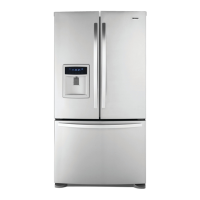
| Model | 795.78516800 |
| Category | Refrigerator |
| Language | English |