Do you have a question about the Kenmore 795.78506800 and is the answer not in the manual?
Essential safety guidelines for servicing the refrigerator and power cord precautions.
Technical specifications, performance metrics, and installation requirements.
List of available replacement parts for the refrigerator.
Standard disclaimer regarding service and interpretation of information.
Step-by-step instructions for removing and replacing refrigerator doors.
Procedures for removing and replacing the evaporator fan and motor.
Steps for disassembling the icemaker and auger motor components.
Instructions for removing and installing the pullout drawer and door ice bin.
Methods for disassembling the water valve and dispenser system.
Details on compressor role, PTC starter, and OLP function.
Procedure for safely removing the PTC cover from the compressor.
Diagnostic flowcharts for compressor and electric component issues.
Troubleshooting guide for common electrical component failures.
Charts correlating complaints with points to check and remedies.
Diagnostic chart for issues related to the refrigeration cycle and its components.
Explanation of the ice maker's operational cycle and modes.
Details on icemaking, harvest, fill modes, and function testing.
Guide to interpreting error codes displayed by the ice maker control panel.
Explanation of display features, lock function, and filter status.
Details on Ultra Ice, dispenser selection, and fan motor controls.
Information on defrost cycles, auto-off lamps, and door open alarms.
Procedures for entering test mode and understanding error code displays.
| Brand | Kenmore |
|---|---|
| Model Number | 795.78506800 |
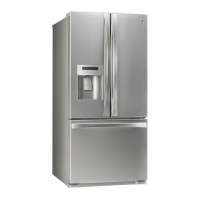
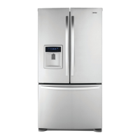
| Type | French Door |
| Ice Maker | Yes |
| Water Dispenser | Yes |
| Energy Star Certified | Yes |
| Refrigerator Capacity | 17.5 cu. ft. |
| Color | Stainless Steel |
| Width | 35.75 in. |
| Height | 69.875 inches |