Do you have a question about the Kenmore 795.78502800 and is the answer not in the manual?
Instructions for safely disconnecting power before servicing the appliance.
List of common replacement parts with their part numbers.
Step-by-step guide for removing and replacing refrigerator doors.
Details procedures for door disassembly and gasket replacement.
Instructions for adjusting and aligning refrigerator doors.
Procedure for removing and replacing the evaporator fan and motor.
Procedure for removing and replacing the defrost control assembly.
Steps for removing and replacing the main printed circuit board (PWB).
Steps for replacing the display printed circuit board (PWB).
Procedure for removing and replacing the icemaker assembly.
Detailed steps for removing and reinstalling the pullout drawer.
Steps for disassembling the fan and fan motor.
Procedure for separating and installing the pull-out drawer.
Explains the role and composition of the compressor.
Details the composition, role, and usage of the PTC starter.
Defines and explains the role of the Overload Protector (OLP).
Troubleshooting guide for compressor and related electrical components.
Troubleshooting guide for other electrical components.
Chart for diagnosing common refrigerator complaints and their remedies.
Troubleshooting chart for the refrigeration cycle.
Diagnostic flowchart for issues within the sealed refrigeration system.
Explains the basic operational principle of the icemaker.
Details the icemaking, harvest, and fill/park modes of the icemaker.
Explains error codes displayed by the ice maker water supply control panel.
Describes the basic function and initial settings of the refrigerator.
Table detailing error codes, their categories, display, and generation factors.
Troubleshooting steps for issues related to poor power source.
Troubleshooting steps for when the refrigerator is not cooling.
Troubleshooting steps for incorrect freezer temperature issues.
Troubleshooting steps for when the refrigerator is cooling poorly.
Troubleshooting steps for defrosting failures.
| Brand | Kenmore |
|---|---|
| Model Number | 795.78502800 |
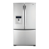
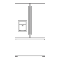
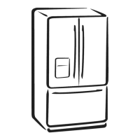
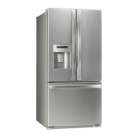
| Type | French Door |
| Ice Maker | Yes |
| Water Dispenser | Yes |
| Energy Star Certified | Yes |
| Color | Stainless Steel |
| Defrost Type | Frost Free |
| Height | 69 3/4 in. |
| Width | 35.75 in. |
| Weight | 280 lbs |