EasyManua.ls Logo

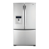
Kenmore 795.78552800 User Manual

Kenmore 795.78552800
54 pages
To Next Page IconTo Next Page
Page #1 background imageLoading...
Page #1 background image
CAUTION
BEFORE SERVICING THE UNIT,
READ THE SAFETY PRECAUTIONS IN THIS MANUAL.
REFRIGERATOR
SERVICE MANUAL
R
795.78542800
795.78543800
795.78544800
795.78546800
795.78549800
795.78552800
795.78553800
795.78554800
795.78556800
795.78559800
795.78712800
795.78713800
795.78719800
795.78722800
795.78723800
795.78729800
P/No. MFL47912401 (Last Revision: March. 10. 2008)
Model #s:

Questions and Answers:

Kenmore 795.78552800 Specifications

General IconGeneral
BrandKenmore
Model795.78552800
CategoryRefrigerator
LanguageEnglish

Summary

1. SPECIFICATIONS

Technical Specifications, Performance, and Installation

Covers electrical specs, performance, refrigeration system, installation, and dimensions.

Parts and Airflow Information

Lists replacement parts and illustrates air circulation diagrams.

3. DISASSEMBLY

3-1 REMOVING AND REPLACING REFRIGERATOR DOORS

Step-by-step guide for removing and reinstalling refrigerator doors.

3-2 DOOR

Procedures related to the refrigerator door and its components.

3-3 TO REMOVE THE DISPENSER

Instructions for removing the water dispenser unit from the refrigerator.

3-4 DOOR ALIGNMENT

Steps to adjust and align the refrigerator doors correctly.

3-5 FAN AND FAN MOTOR

Procedure for removing and disassembling the fan and motor assembly.

3-6 DEFROST CONTROL ASSEMBLY

Steps to remove and replace the defrost control assembly.

3-7 LAMP

Instructions for removing and replacing the compartment lamps.

3-10 HOW TO REMOVE AND REINSTALL THE PULLOUT DRAWER

Detailed instructions for removing and reinstalling the pullout freezer drawer.

3-11 TRIM KIT ASSEMBLY AND DISASSEMBLY METHOD (795.77719,77729 MODELS ONLY)

Procedure for disassembling the left door glass and display unit.

3-11-2 ASSEMBLY AND DISASSEMBLY METHOD OF FREEZER DOOR AND GLASS

Steps for assembling and disassembling the freezer door and glass.

4. ADJUSTMENT

4-1 COMPRESSOR

Details the role, composition, and usage notes for the compressor.

4-2 TSD STARTER

Information on the TSD starter, its application, and electronic circuit.

4-3 OLP (OVERLOAD PROTECTOR)

Definition, role, and cross-section details of the Overload Protector.

5. CIRCUIT DIAGRAM

6. TROUBLESHOOTING

6-1 COMPRESSOR AND ELECTRIC COMPONENTS

Troubleshooting steps for compressor and related electrical components.

6-2 TSD AND OLP

Troubleshooting procedures for the TSD and OLP components.

6-3 OTHER ELECTRICAL COMPONENTS

Troubleshooting for various electrical components affecting cooling performance.

6-4 SERVICE DIAGNOSIS CHART

A chart for diagnosing common complaints and their remedies.

6-5 REFRIGERATION CYCLE

A troubleshooting chart related to refrigerant leaks and clogs.

6-5-1 SEALED SYSTEM DIAGNOSIS

Diagnostic flowchart for 'Not Cooling' complaints related to the sealed system.

7. OPERATION PRINCIPLE & REPAIR METHOD OF ICEMAKER

7-1 OPERATION PRINCIPLE

Explanation of the icemaker's operating modes and principles.

7-2 ICE MAKER FUNCTIONS

Details on start position, ice making, and harvest modes of the icemaker.

7-2-4 Fill/Park Position

Describes the fill and park positions and water supply amounts.

7-2-5 Function TEST

Procedure for performing compulsory tests on the icemaker function.

7-3 DEFECT DIAGNOSIS FUNCTION

Error code diagnosis for the icemaker's water supply control panel.

8. DESCRIPTION OF FUNCTION & CIRCUIT OF MICOM

8-1 FUNCTION

Overview of the refrigerator's main functions and controls.

8-1-6 CONTROL OF FREEZER FAN MOTOR

Details on the freezer fan motor's speeds and operation modes.

8-1-7 Ultra Ice

Explanation of the Ultra Ice function to intensify cooling and increase ice.

8-1-8 REFRIGERATOR LAMP AUTO OFF

Functionality of the refrigerator lamp automatically turning off.

8-1-9 Alarm for Open Door

Description of the door open alarm system and its sounds.

8-1-10 Buzzer Sound

Describes the buzzer sound produced when buttons are pressed.

8-1-11 Defrost cycle

Information on the initiation and termination of the defrost cycle.

8-1-12 Filter Replacement Indication

How the water filter replacement indicator works and how to reset it.

8-1-13 DISPENSER LIGHT

Options for the dispenser light mode, normal or continuous ON.

8-1-13 Automatic Diagnosis Function

How automatic diagnosis works and displays error codes.

8-1-14 TEST Mode

Procedure for using the test mode to check PCB and product functions.

8-2 PCB FUNCTION

Details the power supply circuit for various components of the PCB.

8-2-2 Oscillation Circuit

Describes the circuit generating the base clock for the MICOM.

8-2-3 Reset Circuit

Explains the reset circuit for initializing the MICOM and system functions.

8-2-2 Load / Buzzer Drive & Open Door Detection Circuit

Details circuits for load drive, buzzer, and door open detection.

8-2-3 Temperature Sensor Circuit

Describes the sensor circuits for temperature readings and their states.

8-2-4 Refrigeration Compartment Stepping Motor Damper Circuit

Details the circuit for the stepping motor controlling the compartment damper.

8-3 RESISTANCE SPECIFICATION OF SENSOR

Table listing resistance values for various sensors at different temperatures.

8-3 TROUBLESHOOTING

Troubleshooting steps when the refrigerator's power source is inadequate.

COOLING is poor.

Troubleshooting procedures for general cooling deficiencies.

FREEZER TEMPERATURE is incorrect

Steps to diagnose and resolve incorrect freezer temperature issues.

DEFROSTING is poor.

Diagnostic steps for defrosting failures, including heater, drain, and sensor checks.

Related product manuals