Man-1112 Sigma XT+_23 Page 47 of 52
24. Commissioning instructions
24.1 Before applying power to the panel, any solenoids or igniting actuators must be physically isolated from the
system by disconnecting both wires to it. This will prevent any accidental release of extinguishant.
24.2 When power is applied, if all connections are correct, only the green Power On indicators should be lit.
If any fault indicators are lit the wiring to the appropriate input or output should be checked an all faults
cleared before proceeding.
24.3 Once the panel is fault free, it can be configured with the desired options as
described in section 15 .
24.4 Once the panel has been configured the system should be thoroughly tested to ensure that the control
panels responds as expected and required.
24.5 After satisfactory testing, any final connections should be made (such as to the
extinguishant release actuator).
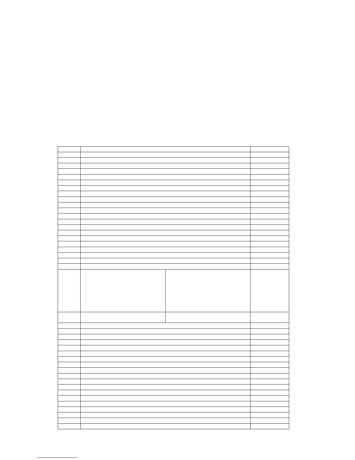
24.6 A record of the configuration options that have been set should be recorded in the tables below and this
manual provided as part of the documentation recommended by BS5839:Part 1:2002 section 40.2 b).
Detection section
CODE FUNCTION TICK IF SET
00 SOUNDER DELAY TIME = 30 SECONDS
01 SOUNDER DELAY TIME = 1 MINUTE
02 SOUNDER DELAY TIME = 2 MINUTES
03 SOUNDER DELAY TIME = 3 MINUTES
04 SOUNDER DELAY TIME = 4 MINUTES
05 SOUNDER DELAY TIME = 5 MINUTES
06 SOUNDER DELAY TIME = 6 MINUTES
07 SOUNDER DELAY TIME = 7 MINUTES
08 SOUNDER DELAY TIME = 8 MINUTES
09 SOUNDER DELAY TIME = 9 MINUTES
10 COMMON ALARM MODE (default)
11 TWO-STAGE ALARM MODE
12 ZONED ALARM MODE
21* DISABLE FIRE BUZZER
22* DISABLE FAULT OUTPUT
23 DISABLE EARTH FAULT MONITORING
24 PULSED REMOTE CONTROL OUTPUT
25 ENABLE SOUNDERS ON DETECTION CIRCUITS
26 DISABLE FIRE OUTPUT
27 DO NOT CHANGE
28 INDICATE CALL POINT ACTIVATION Activation of a call point with a
270R resistance fitted is indicated
by a flashing zone indicator and
“Pu” on the 7 segment display.
Activation of a detector will be
indicated by a steady zone
indicator and nothing on the 7
segment display.
29 DO NOT RE-SOUND ALARMS FROM
ANOTHER ZONE
Silenced sounders will not re-sound
upon further zone activations.
31 ZONE 1 ALARM FROM DETECTOR DELAYED
32 ZONE 2 ALARM FROM DETECTOR DELAYED
33 ZONE 3 ALARM FROM DETECTOR DELAYED
34 ZONE 4 ALARM FROM DETECTOR DELAYED
35 ZONE 5 ALARM FROM DETECTOR DELAYED
36 ZONE 6 ALARM FROM DETECTOR DELAYED
37 ZONE 7 ALARM FROM DETECTOR DELAYED
38 ZONE 8 ALARM FROM DETECTOR DELAYED
41 ZONE 1 ALARM FROM CALL POINT DELAYED
42 ZONE 2 ALARM FROM CALL POINT DELAYED
43 ZONE 3 ALARM FROM CALL POINT DELAYED
44 ZONE 4 ALARM FROM CALL POINT DELAYED
45 ZONE 5 ALARM FROM CALL POINT DELAYED
46 ZONE 6 ALARM FROM CALL POINT DELAYED
47 ZONE 7 ALARM FROM CALL POINT DELAYED
48 ZONE 8 ALARM FROM CALL POINT DELAYED