5
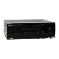
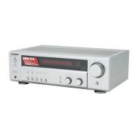
KRF-V5200D
Pin No. Pin Name I/O Description
31 ROUT1 OUT R-ch analog output port from internal DAC1
32 LIN IN L-ch analog input port
33 RIN IN R-ch analog input port
34 PVDD - Power supply for PLL (4.5 to 5.5V)
35 R - External resistor port
36 PVSS - PLL ground
37 RX4 IN No use (receiver channel 4)
38 SLAVE IN Slave mode port. L; master or slave, H; slave
39 RX3 IN Input channel 3. CD/DVD in this model.
40 TST IN Test port
41 RX2 IN Input channel 3. VIDEO 2 in this model.
42 I2C IN Mode selector port. L; 4-serial, H; IIC bus.
43 RX1 IN Input channel 1. DVD/6ch in this model.
44 PDN IN Power down and reset port
*book referred to maker's semiconductor handbook
●
CS493263-CLZ (IC501: X08) Port Description
Pin No. Pin Name I/O Description
1 VD1 - Power supply for digital circuit (+2.5V)
2 DGND1 - Ground for digital circuit
3 AUDATA3 OUT Digital audio output port-3
4 /WR IN This port serves as the active-low data-write-input strobe..
5 /RD - This port serves as the active-low data bus enable.
6 A1 IN Host parallel address bit one
7 A0 IN Host parallel address bit zero
8~11 DATA7~DATA4 - Pulled up
12 VD12 - Power supply for digital circuit (+2.5V)
13 DGND2 - Ground for digital circuit
14~17 DATA3~DATA0 - Pulled up
18 /CS Host parallel chip selector
19 SCDIO IN/OUT Serial control port data input and output
20 /ABOOT OUT Control port automatic boot enable
21 /EXTMEM OUT External memory chip selector port
22 SDATAN1 IN PCM audio data input port-1
23 VD3 - Power supply for digital circuit (+2.5V)
24 DGND3 - Ground for digital circuit
25 SCLKN1 IN PCM audio input bit clock
26 LRCLKN1 IN PCM audio input sampling rate clock
27 CMPDAT IN The compressed data input port when the CDI is confi gured for bursty delivery
28 CMPCLK IN PCM audio input bit clock
CIRCUIT DESCRIPTION

 Loading...


