7
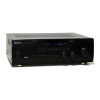
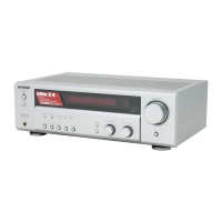
KRF-V5200D
●
Microprocessor: MN101C49KDF (IC601: X08) Port Description
Pin No. Pin Name I/O Description Logic
01 VREF- - A/D converter -ve power supply.
02 TH_DET D1 IN Thermal sensor protection detection 1 A/D
03 DET_F IN Signal level protection detection, front. A/D
04 DET_S IN Signal level protection detection, surround. A/D
05 TH_DET PACK IN Signal level protection detection, pack. A/D
06 TH_DET D2 IN Thermal sensor protection detection 2. A/D
07 FAN_LEVEL IN FAN level A/D
08 TH_DET LR IN Thermal sensor detection L/R A/D
09 S-LEVEL IN RDS signal level detection A/D
10 VREF+ - A/D converter + ve power supply
11 VDD - Microprocessor power supply port
12 OSC2 OUT Microprocessor master clock (8.38MHz)
13 OSC1 IN Microprocessor master clock (8.38MHz)
14 VSS - Microprocessor power supply port
15 XI IN No use
16 XO OUT No use
17 /MMOD IN Memory mode switch input port Always “L”
18 FL_DIN OUT FL driver data input
19 FL_D0 IN FL driver data output
20 FL_CLK OUT FL driver clock
21~23 NC OUT No use
24 /-6dB_ATT OUT -6dB ATT Active “L”
25 /NC OUT No use Active “L”
26 REMOCON IN Remote control input (interrupt)
27 RDS_CLK IN RDS clock input (interrupt)
28 RDS_DATA IN RDS data input
29 CODEC_INT IN DIR error detection input (interrupt)
30 DIGITAL_DET IN DIGITAL detection input Active “H”
31 DSP_INTREQ IN DSP interrupt request input
32 NC (For FLASH µ-com) IN No use
33 /RESET IN Microprocessor reset Active “L”
34 A_MUTE OUT Audio mute
35 LIMITER OUT Limiter
36 FAN_CONT OUT FAN control
37 AMP PROT IN AMP protection
38 AVR PROT IN AVR protection
39 HP RLY OUT Headphone relay
40 FA RLY OUT Front relay
41 NC (For FLASH µ-com) OUT No use
42~44 NC OUT No use
CIRCUIT DESCRIPTION

 Loading...