MDX-F1
5
CIRCUIT DESCRIPTION
1. Initialization
1-1 Setting
Insert the AC power cord with pressing the REPEAT key.
1-2 Operation
Display shows "INITIALIZE" if the unit works in initializa-
tion mode. It shows "STANDBY" after the unit is end of
work.
The unit is shipment condition(MD disc comes out, RAM
is clear, Backup data is also.) if normal mechanisms are
initialization.
Display shows error message as follows if the every
mechanism has an initialization error and CD door switch
malfunction.
Error
CD The first digit: C
MD The third digit: M
CASSETTE The 5th digit: X
CD DOOR SW The 7th digit: S
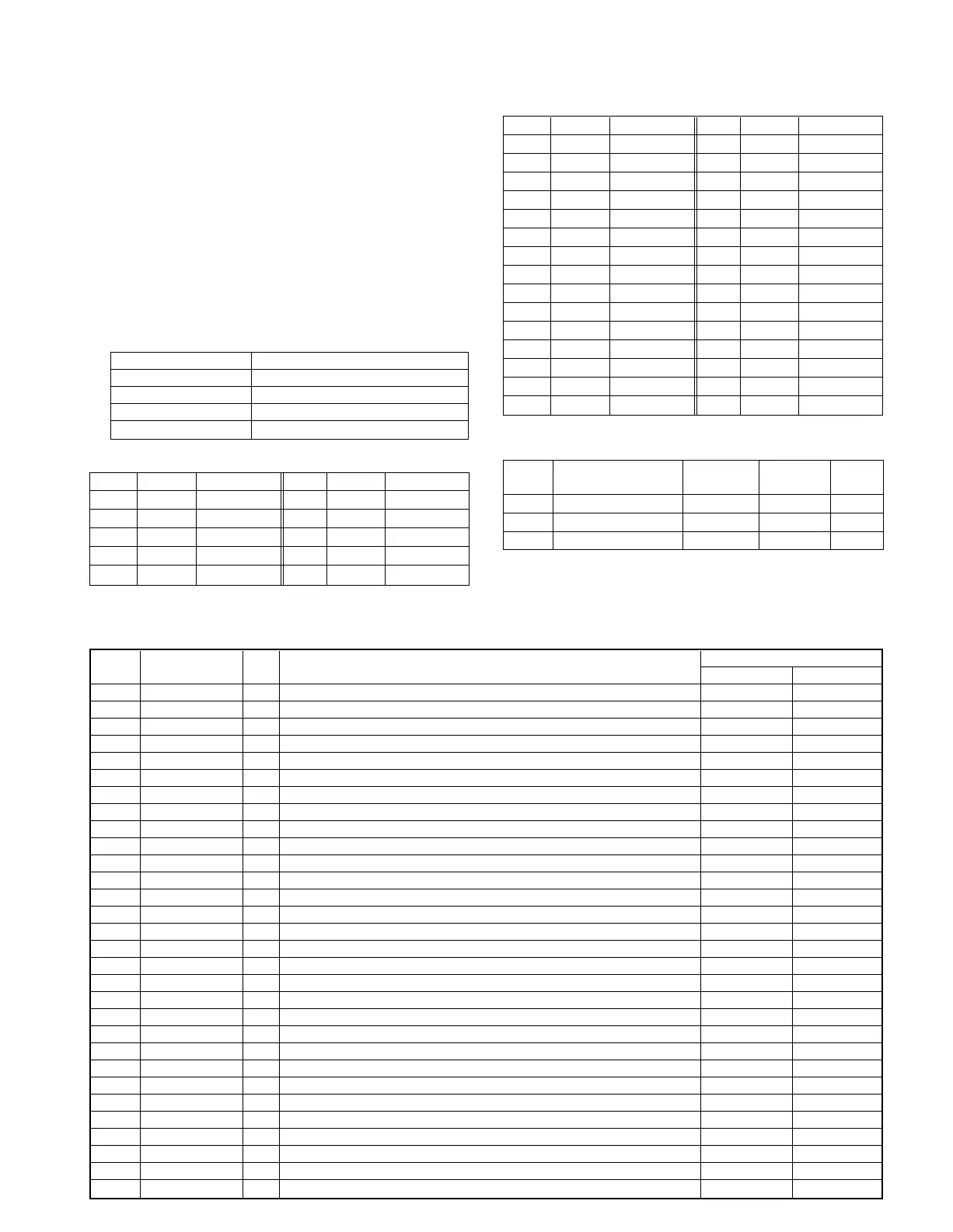
2. TUNER Preset
3. TUNER SPECIFICATIONS
P.CH BAND FREQ P.CH BAND FREQ
1 FM 83.50MHz 6 FM 90.00MHz
2 FM 76.00MHz 7 FM 76.00MHz
3 FM 89.10MHz 8 AM 1629kHz
4 FM 108.00MHz 9 AM 1602kHz
5 FM 91.50MHz 10 AM 999kHz
P.CH BAND FREQ P.CH BAND FREQ
11 AM 630kHz 26 FM 76.00MHz
12 AM 1440kHz 27 FM 76.00MHz
13 FM 106.00MHz 28 FM 76.00MHz
14 AM 531kHz 29 FM 97.50MHz
15 FM 76.00MHz 30 FM 106.00MHz
16 FM 91.50MHz 31 FM 76.00MHz
17 FM 92.50MHz 32 FM 76.00MHz
18 FM 76.00MHz 33 FM 76.00MHz
19 AM 990kHz 34 FM 76.00MHz
20 FM 91.40MHz 35 FM 76.00MHz
21 AM 531kHz 36 FM 76.00MHz
22 FM 76.00MHz 37 FM 76.00MHz
23 FM 76.00MHz 38 FM 76.00MHz
24 FM 76.00MHz 39 FM 108.00MHz
25 FM 76.00MHz 40 AM 945kHz
BAND
RECEIVING CHANNEL
IF PLL
FREQ. SPACE
FM 76.0MHz~87.5MHz 100kHz -10.7MHz 25kHz
FM 87.5MHz~108MHz 50kHz -10.7MHz 25kHz
AM 531kHz~1629kHz 9kHz +450kHz 9kHz
ACTIVE
Port # Port Name I/O Descriptions
HL
1 DSTP O CD disc motor servo control output port OFF ON
2 XLON O Bias control port ON OFF
3 LDC O LD control OFF ON
4 SCLK O CD sense data read clock
5 SENSE I CD sense input 1 0
6 CD CLK O Clock for CD DSP
7 XLAT O CD DSP latch output
8 BYTE I GND
9 CNVSS I GND
10 XCIN I Timer clock(32.768kHz)
11 XCOUT O Timer clock(32.768kHz)
12 RESET I Microprocessor reset signal input NORMAL RESET
13 XOUT O Main clock port
14 VSS - GND
15 XIN I Main clock port (10MHz)
16 VCC(B.U.) - Power supply port (+5V)
17 NMI I +5.0V
18 REMOCON I Remote control signal input port
19 NC O open
20 SCOR I Sub-code synchro signal port
21 XRST O CD DSP reset signal output port NORMAL RESET
22 PLL DO I PLL data input port
23 SA CE O PLL IC chip enable
24 SA CLK O PLL IC clock
25 SA DATA O PLL IC data output port
26 ST I Stereo sensor port for tuner MONO STEREO
27 SD I SD sensor port for tuner UNTUNED TUNED
28 SQCK O Sub-code clock for CD
29 SQSO I Sub-code input port for CD
30 NC O open
4. MAIN MICROPROCESSOR: M30622MC-746(X09,IC601)
4-1 Port descriptions

 Loading...