EasyManua.ls Logo

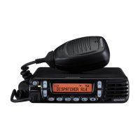
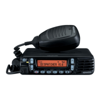
Kenwood NX-700 Service Manual

Kenwood NX-700
109 pages
To Next Page IconTo Next Page
Page #1 background imageLoading...
Page #1 background image
This product uses Lead Free solder.
This product complies with the RoHS directive for the European market.
SERVICE MANUAL
© 2008-4 PRINTED IN JA PAN
B51-8822-00
(
N
)
446
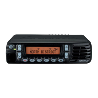
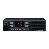
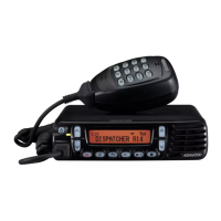
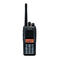
NX-700/700H
VHF DIGITAL TRANSCEIVER
GENERAL .....................................................2
SYSTEM SET-UP .........................................4
REALIGNMENT ...........................................5
INSTALLATION ............................................7
DISASSEMBLY FOR REPAIR ....................14
CIRCUIT DESCRIPTION ............................17
COMPONENTS DESCRIPTION .................23
PARTS LIST ...............................................26
EXPLODED VIEW ......................................39
PACKING ....................................................40
TROUBLE SHOOTING ..............................41
ADJUSTMENT ..........................................44
TERMINAL FUNCTION .............................62
PC BOARD
DISPLAY UNIT (X54-3640-10) ...............72
TX-RX UNIT (X57-7380-XX) (A/2) ........74
TX-RX UNIT (X57-7380-XX) (B/2) ........78
INTERCONNECTION DIAGRAM ..............79
SCHEMATIC DIAGRAM ............................80
BLOCK DIAGRAM .....................................98
LEVEL DIAGRAM ....................................100
SPECIFICATIONS ...................BACK COVER
Panel assy
(A62-1162-03)
Key top
(K29-9401-03)
Cover
(A01-2194-11)
Microphone
(T91-0639-35)
CONTENTS

Table of Contents

Other manuals for Kenwood NX-700

Question and Answer IconNeed help?

Do you have a question about the Kenwood NX-700 and is the answer not in the manual?

Kenwood NX-700 Specifications

General IconGeneral
PurposeDigital Mobile Radio (DMR)
Maximum range- m
Operating frequency136 - 174 MHz
ShockproofYes
Product colorBlack
International Protection (IP) codeIP54
Display typeLCD
Operating temperature (T-T)-30 - 60 °C
Weight and Dimensions IconWeight and Dimensions
Depth157 mm
Width160 mm
Height45 mm
Weight1380 g

Summary

NX-700/700H General Information and Safety

Personal Safety Precautions

Recommended safety precautions for operating the transceiver.

General Installation Planning

Service Information

Reference to manual sections for servicing the radio.

Realignment and Mode Operations

PC Mode Operations

Using PC mode for transceiver programming and data management.

Firmware Programming and Cloning

Firmware Programming Mode

Procedure for programming the transceiver's firmware.

Programming Firmware

Detailed steps for the firmware programming process.

Clone Mode Operation

Procedure for cloning transceiver data between units.

Installation Procedures

Ignition Sense Cable Installation

Connecting the optional ignition sense cable (KCT-46).

Installing Optional Accessories

Control Head Remote Kit Installation

Voice Guide and Storage Unit Installation

External Speaker Installation

GPS Receiver Installation

GPS Receiver and VGS-1 Installation

Disassembly and Reassembly Precautions

Precautions on Disassembly

Important safety and handling precautions before disassembling.

TX-RX PCB Disassembly

Detailed steps for removing the TX-RX PCB.

Speaker Hardware Fixture Removal

Steps to remove the speaker assembly.

PCB Reassembly Procedures

Precautions on Reassembly

Guidelines for correctly reassembling the transceiver.

TX-RX PCB Reassembly

Steps to reinstall the TX-RX PCB.

Component Removal and Installation

Circuit Description Overview

Frequency Configuration

Explanation of the transceiver's frequency stages.

Receiver System Description

Detailed description of the receiver circuitry.

Transmitter and Control Circuitry

Transmitter System Overview

Detailed description of the transceiver's transmitter circuitry.

Synthesizer and Control Circuitry

PLL Frequency Synthesizer

Explanation of the Phase-Locked Loop frequency synthesizer.

Control and Power Supply Circuits

Control Circuit Overview

Description of the transceiver's control circuitry.

Power Supply Circuit Description

Description of the transceiver's power supply system.

Signaling and Compander Circuits

Signaling Circuit Overview

Description of signaling circuits for QT, DQT, DTMF, etc.

Component Descriptions

Display Unit Components

List of components for the display unit (X54-3640-10).

TX-RX Unit Components

List of components for the TX-RX unit (X57-7380-XX).

Parts List Details

Display Unit Parts List

Parts list for the display unit (X54-3640-10).

TX-RX Unit Parts List

Display Unit Parts List (Continued)

Continuation of the parts list for the display unit.

Parts List Continuation

TX-RX Unit Parts List (Continued)

Continuation of the parts list for the TX-RX unit.

Exploded View Diagram

Troubleshooting BGA IC Faults

Checking Power Supply Voltages

Procedure to check voltage levels of key ICs.

Checking Clock Signals

Procedure to check clock signals for proper operation.

Checking Reset and Control Signals

Checking essential control signals to the ASIC.

Checking ASIC Control Signals

Verifying control signals fed into the ASIC.

Checking ASIC Input Switch Signals

Verifying ASIC input signals related to switches.

Checking ASIC Output Signals

Verifying output signals from the ASIC.

Troubleshooting Procedures

Checking ASIC Output via Software

Verifying ASIC signal outputs using software control.

Panel Control Troubleshooting (TX-RX Unit)

Troubleshooting panel control signals on the TX-RX unit.

Panel Control Troubleshooting (Panel Unit)

Troubleshooting panel control signals on the panel unit.

Control Signal Verification

Verifying control signals for the display.

Display Control Signal Verification

Verifying the display control signals.

LCD Error Message Interpretation

Interpreting and resolving LCD error messages.

TX-RX Unit Replacement and PCB Handling

Post-PCB Replacement Procedures

Procedures to follow after replacing the printed circuit board.

PCB Replacement Steps

Steps after replacing the printed circuit board.

Using KPG-111D for Configuration

Using the programming software for configuration.

Entering Test Mode for Adjustments

Entering test mode for adjustments.

Applying New Labels

Applying new labels to the replaced PCB.

Writing FPU Data (Optional)

Writing FPU data with KPG-111D if necessary.

Transceiver Adjustment Procedures

Panel Test Mode Operations

Features and operation of the panel test mode.

Frequency and Signaling Adjustments

Frequency and Signaling Overview

Adjusted frequencies and signaling modes.

Panel Tuning Mode Procedures

Procedures for tuning the transceiver in panel mode.

Entering Transceiver Tuning Mode

Steps to enter and navigate tuning mode.

Transmitter Adjustment Items

5 Reference Level Frequencies

Frequencies used for 5 reference level adjustments.

Adjustment Items and Display

Table of adjustable items and their display parameters.

Transmitter Adjustment Details

Adjustable Items and Ranges

Detailed list of adjustable items and ranges.

Signal Deviation Adjustments

Transmitter Section Adjustments (Continued)

Continuation of transmitter parameter adjustments.

Balance Adjustment

Adjusting the transmitter balance for signaling.

Maximum Deviation (NXDN) Adjustment

Adjusting deviation for NXDN signals.

Maximum Deviation (Analog) Adjustment

Adjusting deviation for analog signals.

Alignment Test Equipment and Setup

Test Equipment Required for Alignment

List of required test equipment and their specifications.

Radio Check Procedures

Radio Check Section

Procedures for radio performance checks.

Frequency Check Procedure

Procedure for checking frequency accuracy.

High Power Check Procedure

Procedure for checking high power output.

Low Power Check Procedure

Procedure for checking low power output.

MIC Sensitivity Check Procedure

Procedure for checking microphone sensitivity.

Receiver Adjustment Procedures

Receiver Section Adjustments

Procedures for adjusting receiver parameters.

AF Level Setting

Adjusting the audio output level.

Sensitivity 1 Adjustment (BPF)

Adjusting receiver sensitivity 1, related to BPF.

Sensitivity 2 Adjustment (BPF)

Adjusting receiver sensitivity 2, related to BPF.

RSSI Reference Adjustment

Adjusting RSSI reference levels for analog signals.

Common Adjustment Section

Common adjustment procedures applicable to multiple sections.

Receive Assist Adjustment

Adjusting receive assist parameters.

Transmit Assist Adjustment

Adjusting transmit assist parameters.

RTC Oscillation Frequency Adjustment

Adjusting the real-time clock frequency.

Transmitter Adjustment Procedures

Receiver Section Adjustment (Continued)

Further receiver parameter adjustments.

Frequency Adjustment Procedure

Procedure for adjusting the transceiver frequency.

Transmitter Section Adjustments

Procedures for adjusting transmitter parameters.

High Transmit Power Limit Adjustment

Adjusting the high power limit for the transmitter.

Transmitter Power Adjustments

Low Transmit Power Limit Adjustment

Adjusting the low power limit for the transmitter.

High Transmit Power Adjustment

Adjusting the high transmit power output.

Low Transmit Power Adjustment

Adjusting the low transmit power output.

Analog Deviation and Signal Adjustments

QT Deviation Adjustment

Adjusting QT deviation for signals.

DQT Deviation Adjustment

Adjusting DQT deviation for signals.

Signal Deviation Adjustments (Continued)

LTR Deviation Adjustment

Adjusting LTR deviation for signals.

CWID Deviation Adjustment

Adjusting CWID deviation for signals.

DTMF Deviation Adjustment

Adjusting DTMF deviation for signals.

Necessary Deviation Adjustment Order

Order of deviation adjustments for different signal types.

Single Tone Deviation Adjustment

Adjusting single tone deviation.

MSK Deviation Adjustment

Adjusting MSK deviation for signals.
Receiver Adjustment Details

Receiver Sensitivity Adjustments

Receiver Sensitivity Adjustments (Continued)

Terminal Function Descriptions

Terminal Function Details

Connector Specification Details

Terminal Function Details (Continued)

CN595 Connector Specification Details

CN595 Connector Function Details

D-sub 25-pin Connector Specification

D-sub 25-pin Connector Specification (Continued)

Interconnection Diagram

Schematic Diagrams

Schematic Diagrams (Continued)

Block Diagram

Block Diagram (Continued)

Level Diagram

Level Diagram (Continued)

Specifications

Related product manuals