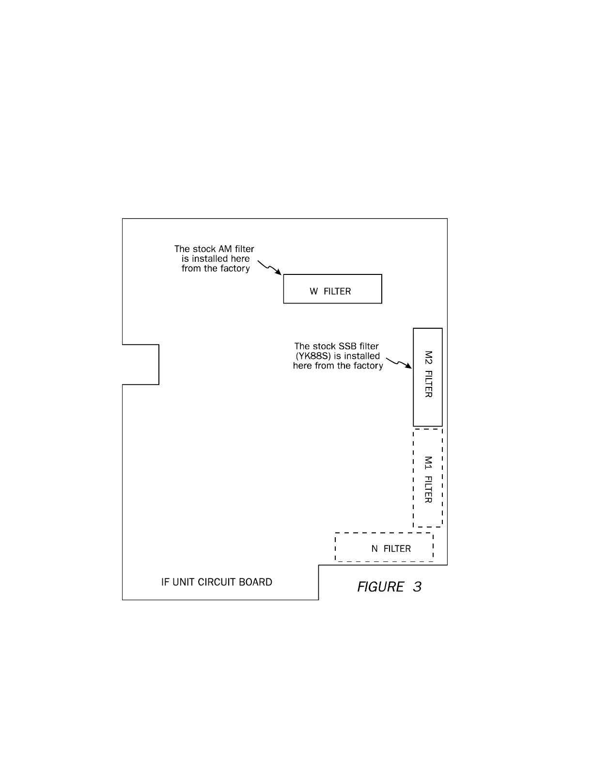
INSTALLING FILTERS
Installing the optional filters is easy. The IF board is labeled with each filter position as
shown in Figure 3. Simply locate the proper position for the filter you wish to install and feed the
leads through the board. The filter will only go in one way. Solder the leads with a low wattage
iron as quickly as possible to prevent damage to the board. Each filter position also has a wire
with a jumper pin to tell the microprocessor that a filter is installed. These jumpers are labeled
(for example M1 FILTER), and when you install a filter you move the jumper pin from NO to
YES.
The YK88A1 AM filter is much easier to install. It is mounted with screws and uses
connectors to interface to the board. Simply remove the old filter and mate the new filter with the
connectors and screw into place.
9

 Loading...