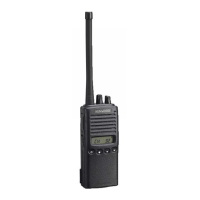
Do you have a question about the Kenwood TK-272G and is the answer not in the manual?
| frequency range | 150~174MHz (K) 136~150MHz (K2) |
|---|---|
| number of channels | Max. 32 |
| channel spacing | 25kHz, 30kHz (Wide) 12.5kHz, 15kHz (Narrow) |
| PLL channel stepping | 2.5kHz, 5kHz, 6.25kHz, 7.5kHz |
| operating voltage | 7.5 VDC±20% |
| battery life with KNB-14 | More than 4 hours at 5 watts (5-5-90 duty cycle) |
| battery life with KNB-15A | More than 8 hours at 5 watts (5-5-90 duty cycle) |
| operating temperature range | -30˚C to +60˚C (-22 ˚F to +140 ˚F) |
| sensitivity EIA 12dB SINAD | 0.25µV (Wide)/0.28µV (Narrow) |
|---|---|
| selectivity | 70dB (Wide)/65dB (Narrow) |
| inter modulation | 65dB (Wide)/60dB (Narrow) |
| spurious response | 65dB |
| audio power output | 500mW |
| frequency stability | ±3.0ppm |
| channel frequency spread | 24MHz (K), 14MHz (K2) |
| RF power output | 5W/1W |
|---|---|
| spurious and harmonics | 70dB |
| modulation | 16KφF3E (Wide)/11KφF3E (Narrow) |
| FM noise | 45dB (Wide)/43dB (Narrow) |
| audio distortion | Less than 5% |
| frequency stability | ±3.0ppm |
| channel frequency spread | 24MHz (K), 14MHz (K2) |
| dimensions with KNB-14 | 58 W x 135 H x 32 D mm |
|---|---|
| weight with KNB-14 | 400g (0.88lbs) |
| dimensions with KNB-15A | 58 W x 135 H x 35 D mm |
| weight with KNB-15A | 440g (0.97lbs) |
Manual scope, intended use, and ordering parts information.
Safety precautions for handling equipment and operating safely.
Guidance on servicing procedures using diagrams and procedures.
Steps for setting up the transceiver, including software and hardware.
Describes the front panel controls and indicators of the transceiver.
Details functions programmable to auxiliary keys for user customization.
Explains the meaning of icons displayed on the LCD screen.
Details how to use the scanning function, including scan types.
Describes specific features like Time-out Timer and PTT ID.
Explains DTMF and 2-Tone signaling options and their settings.
Lists and describes different operating modes for realignment.
Explains the procedure to enter different operating modes.
Refers to adjustment section for panel test mode settings.
Describes the checksum function for verifying data.
Details using PC mode for programming and data transfer.
Explains how to upgrade the transceiver's firmware.
Describes cloning data between transceivers.
Explains self-programming mode for frequency and signaling settings.
Explains how to reset function data to default values.
Steps to separate the radio's case from its chassis.
Steps to detach the chassis from the main unit.
Explains the frequency configuration of the transceiver.
Describes the receiver section and its frequency configuration.
Details the IF amplifier circuit and signal processing.
Explains the circuit for switching between wide and narrow modes.
Describes the audio amplifier circuit and its components.
Explains the squelch circuit and its operation.
Details signaling methods like QT/DQT, 2-TONE, and DTMF.
Explains the PLL circuit for frequency synthesis.
Describes the unlock detector circuit and its function.
Details the transmitter system, including microphone and amplifier circuits.
Explains the control circuit managed by the microprocessor.
Lists terminals for optional board connections.
Details the LCD driver IC and its block diagram.
Block diagram for the LCD driver.
Explains the pin functions of the UPB1509GV (IC301).
Details the microprocessor IC and its pin functions.
Explains the pin functions of the BU4094BCFV shift register.
Explains the pin functions of the second BU4094BCFV shift register.
Lists and describes components for the display unit.
Lists and describes components for the TX-RX unit.
Parts list for the TK-272G model.
Parts list for the display unit.
Parts list for the TX-RX unit.
Provides an exploded view of the transceiver assembly.
Illustrates the packing configuration for shipping and storage.
Lists necessary test equipment and their specifications for alignment.
Lists parts needed for alignment procedures.
Details the chassis repair jig and its usage.
Describes the extension flat cable repair jig.
Explains how to enter and use test mode for adjustments.
Details frequency and signalling settings for tuning.
Explains the LCD display during test mode operations.
Explains the LCD display during tuning mode operations.
Provides panel tuning data for K type transceivers.
Provides panel tuning data for K2 type transceivers.
Flowchart detailing the tuning mode adjustments.
Covers common adjustments like setting voltage and VCO lock.
Details adjustments for transmitter functions like frequency, power, and sensitivity.
Details the battery detection writing procedure.
Describes checking battery detection status.
Explains sensitivity adjustment procedures and expected values.
Covers Band-Pass Filter adjustments and waveforms.
Checks sensitivity under different conditions.
Adjusts squelch opening threshold.
Adjusts squelch closing threshold.
Checks squelch operation.
Shows component layout on the display unit's component side.
Shows component layout on the display unit's foil side.
Shows component layout on the TX-RX unit's component side.
Shows component layout on the TX-RX unit's foil side.
Shows combined component layout for TX-RX unit.
Provides the overall schematic diagram of the transceiver.
Details the KMC-17 speaker microphone and its parts.
Lists parts for the KMC-17 speaker microphone.
Details the KMC-21 speaker microphone and its parts.
Lists parts for the KMC-21 speaker microphone.
General specifications including frequency range, channels, and battery life.
Receiver specifications like sensitivity, selectivity, and audio power.
Transmitter specifications like RF power output and frequency stability.
 Loading...