TM-V708A
11
CIRCUIT DESCRIPTION
The AF signal output combinations are as in the speaker
combination table on the below.
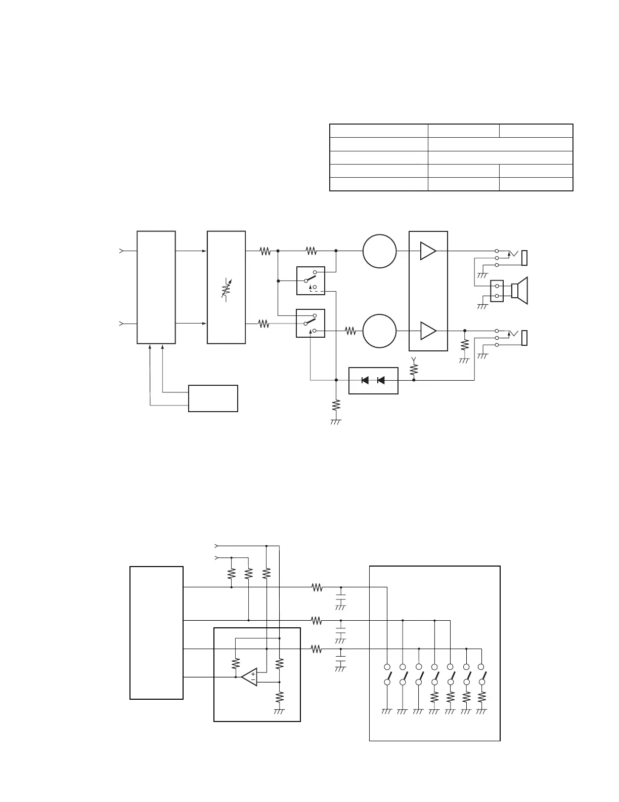
Fig. 15 Microphone key input circuit
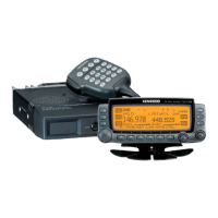
Fig. 14 Speaker switching circuit
CROSS POINT SW
AO 1
AO 0
CPU
R857 R874
R870
R873
R872
R875
R858
IC 808
IC807
Q804
Q805
MUTE
MUTE
D803
J801
J802
CN800
IC806
POWER AMP
BEEP
DTMF
RAV
RAU
IC702
IC804
IC604
ELECTRONIC
VOLUME
13 8
16
1
1
7
7
5
5
6
MIC PTT
MIC UP
MIC DW
INT3
MICRO
PROCESSOR
M 5C
5C
R806
R804
R803
R805
MIC
100K
100K
22K
22K
IC604
R683
R684
R685
IC800
R812
R808
C801
C800
C802
PTT
UP
DOWN
CALL
VFO
MR
PF
KEY INPUT INTERRUPT CIRCUIT
6-2. Speaker Switching Circuit
There are two speaker jacks, J801 and J802. The AF
signals can be output in various combinations matching the
internal speakers.
When no external speaker is connected to J801, Pins 5 of
the multiplexer (IC807, IC808) go low, the AF signals AO 0
and AO 1 are added and input to the power amp (IC806).
When an external speaker is connected to J801, Pins 5 of
the multiplexer (IC18) go high and AO 0 and AO 1 are input
separately to the power amp.
6-3. Microphone Key Input
The microphone UP/DOWN and function keys are
connected to the microprocessor analog input. The voltage
when a key is ON operates the corresponding function. Also,
the key input interrupt circuit is for switching the power ON/
OFF with the microphone. When the DOWN, MR, and PF
keys are pressed, an interrupt is generated and the
microprocessor is awoken from stop mode. However, with
the TM-V708A, the power ON/OFF switch function can be
registered to the PF key on the microphone.
AO 1 AO 0
Internal speakers only Internal speaker
1 external speaker (J802) external speaker
1 external speaker (J801) Internal speaker external speaker
2 external speaker external speaker external speaker
Table5 Speaker combination table
 Loading...