TM-V708A
3
CIRCUIT DESCRIPTION
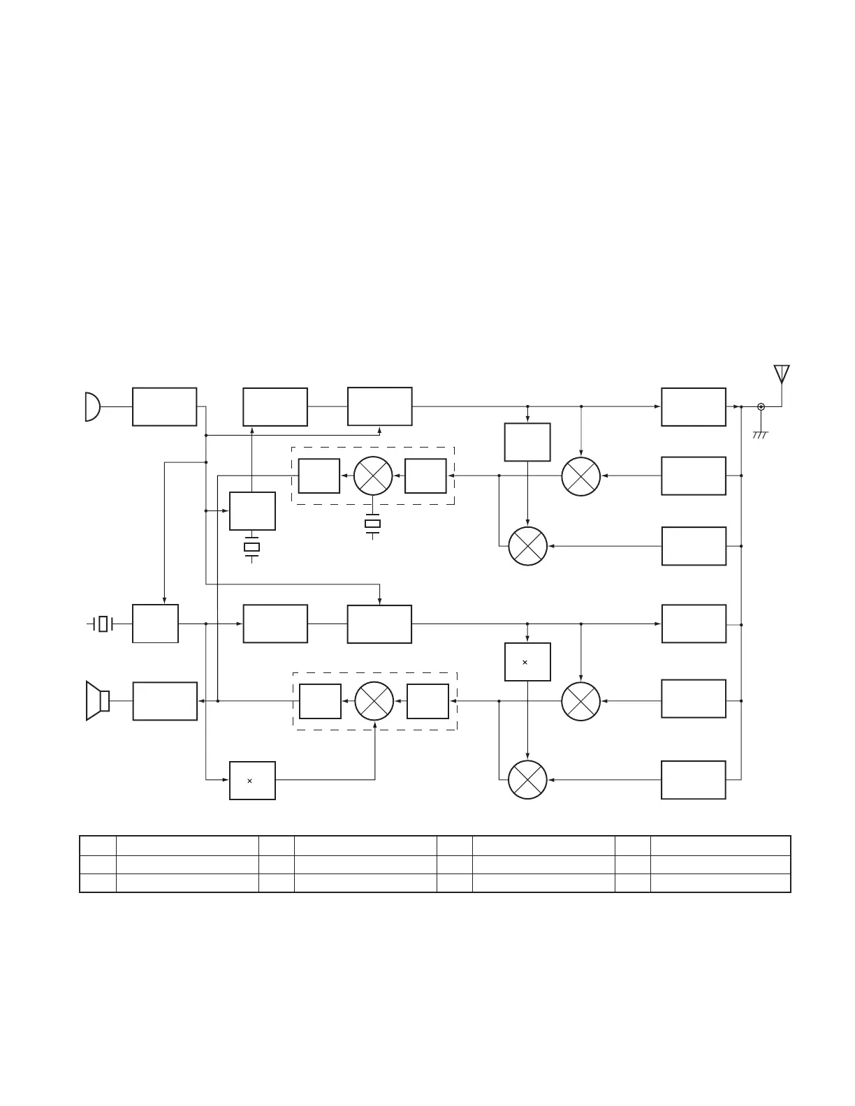
1. Frequency configuration
The TM-V708A has an individual VCO and PLL unit for
both VHF and UHF bands. Using these separate VCO and
PLL circuit, it can receive 2 separate bands at the same time.
Also, you can perform the full-duplex operation.
The VHF VCO is used for the following functions:
(i) VHF transmission
(ii) The first local oscillator for the main band (VHF) reception.
(iii)The first local oscillator for the sub band (UHF)
reception (doubled).
The UHF VCO is used for the following functions:
(i) UHF transmission
(ii) The first local oscillator for the main band (UHF) reception.
(iii)The first local oscillator for the sub band (VHF)
reception (halved).
The PLL reference frequency is generated by a 12.8MHz
crystal oscillator connected to the VHF and UHF PLL ICs. This
reference frequency is used for both PLL circuits.
The second local oscillator for the VHF band uses the
tripled 12.8MHz reference oscillator frequency. The
45.05MHz second local oscillator for the UHF band is
generated by the IF IC crystal oscillator circuit.
MIC AMP
MIC
SP
OSC
OSC
AF AMP
PLL 1
PLL 2
VCO 1
VCO 2
DET
DET
IF 1
IF 2
1/2
2
3
Crystal
12.8MHz
12.8MHz
Crystal
12.8MHz
Crystal
45.505MHz
2nd IF
455kHz
2nd IF
450kHz
1st IF
45.05MHz
1st IF
38.85MHz
AF
AF
A
B
F
C
I
E
D
G
J
L
H
K
38.4MHz
ANT
UHF TX
UHF RX
UHF RX
MAIN
MAIN
SUB
SUB
VHF RX
VHF RX
VHF TX
Fig. 1 Frequency configuration
A 438.000~449.995MHz D 144.000~147.995MHz G 392.950~404.945MHz J 182.850~186.845MHz
B 438.000~439.995MHz E 144.000~145.995MHz H 378.100~382.090MHz K 195.575~200.5725MHz
C 144.000~147.995MHz F 438.000~449.995MHz I 189.050~193.045MHz L 399.150~411.145MHz
 Loading...