EasyManua.ls Logo

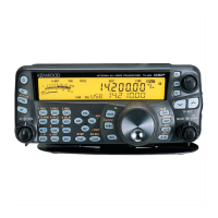
Kenwood TS-2000 Service Manual

Kenwood TS-2000
171 pages
To Next Page IconTo Next Page
Page #1 background imageLoading...
Page #1 background image
© 2000-12 PRINTED IN JAPAN
B51-8558-00
(
N
)
889
ALL MODE MULTI-BAND TRANSCEIVER
TS-2000/X
SERVICE MANUAL
CIRCUIT DESCRIPTION ............................. 2
DESCRIPTION OF COMPONENTS ......... 24
SEMICONDUCTOR DATA ....................... 34
PARTS LIST .............................................. 51
EXPLODED VIEW..................................... 93
PACKING .................................................. 97
ADJUSTMENT ......................................... 98
TERMINAL FUNCTION .......................... 124
WIRING.................................................. 133
PC BOARD VIEWS / CIRCUIT DIAGRAMS
FILTER UNIT (X51-315X-XX) ............. 135
FINAL UNIT (X45-360X-XX) .............. 137
DISPLAY UNIT (X54-3320-00) ........... 151
CONTROL UNIT (X53-391X-XX) ....... 155
TX-RX 1 UNIT (X57-605X-XX)........... 169
TX-RX 2 UNIT (X57-606X-XX)........... 186
TX-RX 3 UNIT (X57-6070-00) ............ 209
BLOCK DIAGRAM .................................. 223
LEVEL DIAGRAM ................................... 229
MC-52DM ............................................... 233
UT-20 ..................................................... 235
RC-2000 ................................................. 235
ARCP-2000 ............................................ 235
SPECIFICATIONS ................................... 236
Knob
(K21-1104-03)
Knob ring
(K29-5395-04)
Knob
(K29-5397-13) x 2
Knob
(K29-5398-03) x 3
Knob
(K29-5399-03) x 3
Knob
(K29-5396-03) x 2
Key top
(K29-5391-02)
Key top
(K29-5393-12)
Key top
(K29-5394-12)
Key top
(K29-5392-12)
Front glass
(B10-2608-02)
Cabinet (Upper)
(A01-2176-01)
Foot
(J02-0442-04) x 2
Foot
(J02-0440-04)
RF coaxial receptacle (Round)
(E06-0858-15)
Phone jack (9P)
(E11-0438-05)
CONTENTS

Other manuals for Kenwood TS-2000

Questions and Answers:

Kenwood TS-2000 Specifications

General IconGeneral
Antenna Impedance50 ohms
Supply Voltage13.8V DC ±15%
Current Drain TX20.5A
Receiver TypeTriple Conversion Superheterodyne
ModesSSB, CW, AM, FM, FSK
TypeBase Station
Frequency Range TX0.1-60 MHz (HF), 144-148 MHz (VHF), 430-450 MHz (UHF)
Image RejectionMore than 70 dB
Selectivity2.4 kHz (SSB), 500 Hz (CW), 15 kHz (FM)
Antenna ConnectorSO-239
Frequency RangeHF/6m/2m/70cm

Summary

CIRCUIT DESCRIPTION

Overview of the Operation

General overview of the TS-2000/X transceiver operation with IF/AF DSP.

Frequency Configuration

Details frequency conversion methods for transmission and reception modes, illustrated by Fig. 1.

HF/50MHz LO1

Describes the local oscillator LO1 circuit for HF and 50MHz bands, including frequency generation.

1.2GHz Unit Local Oscillator

Explains the local oscillator circuit for the 1.2GHz band, including its frequency configuration.

SEMICONDUCTOR DATA

Main CPU : 64F2633xxxx (Control unit IC8) Pin Function

Details the pin functions and specifications of the main CPU (IC8).

CODEC (16 bit) : AK4518 (Control unit IC522,523) Pin Function

Explains the pin functions and block diagram of the 16-bit CODEC (IC522,523).

PARTS LIST

FINAL UNIT (X45-360X-XX) (A/2)

Lists the parts for the HF/VHF final amplifier unit (X45-360X-XX).

FILTER UNIT (X51-315X-XX)

Lists the parts for the filter unit (X51-315X-XX).

PC BOARD VIEWS / CIRCUIT DIAGRAM

FILTER UNIT (X51-315X-XX) Component/Foil Side

Shows the component and foil sides of the filter unit PCB.

FINAL UNIT (X45-360X-XX) (B/2) Component/Foil Side

Displays the component and foil sides of the UHF final unit PCB.

ADJUSTMENT

Preparation

Describes the necessary preparations and initial settings for adjustment procedures.

Adjustment Mode Operation Procedure

Outlines the steps for entering and operating the adjustment mode.

Procedure for writing adjustment firmware

Details the steps for uploading adjustment firmware to the unit.

PLL Section

Covers the adjustment procedures for various PLL circuits, including VHF MAIN PLL and SUB PLL.

TERMINAL FUNCTION

FINAL UNIT (X45-360 A/2)

Details the functions of the terminals on the final unit (X45-360 A/2).

CONTROL UNIT (X53-391)

Explains the terminal functions for the control unit (X53-391).

BLOCK DIAGRAM

LEVEL DIAGRAM

SPECIFICATIONS

Related product manuals