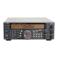
Do you have a question about the Kenwood TS-570D and is the answer not in the manual?
| Receiver Type | Superheterodyne |
|---|---|
| Antenna Impedance | 50 ohms |
| Image Rejection | More than 70 dB |
| Power Supply | 13.8 V DC ±15% |
| Current Drain RX | 1.5 A |
| Frequency Range RX | 0.5-30 MHz |
| Modes | SSB, CW, AM, FM |
| RF Power Output | 100 W (SSB/CW/FM), 25 W (AM) |
| IF Rejection | >70 dB |
| Current Drain TX | 20 A |
Details the TS-570D's frequency configuration using double/triple conversion and PLL.
Explains the Phase Locked Loop circuit, DDS, and LO generation for frequency control.
Describes the double conversion receiver architecture and signal path from antenna to output.
Details the signal flow from microphone input to output for SSB, AM, FM, and CW modes.
Explains the DSP, EPROM, clock logic, and CODEC functions in the digital unit.
Covers digital signal processing for SPAC, line enhancer, and beat cancel functions.
Lists key components like amplifiers, switching elements, regulators, and diodes in the final unit.
Details components like CPU, EEPROM, multiplexers, amplifiers, and CODEC in the control unit.
Lists transistors, ICs, and diodes used in the TX-RX unit for various functions.
Details the pin functions and connections for the CXD1095Q IC.
Provides the terminal connection diagram and functions for the AK4506-VS CODEC IC.
Details the pin connections for the ADSP2181KS-115 DSP IC.
Shows the circuit diagram and terminal connections for the KCD10 HIC.
Lists all components and their part numbers for the final unit of the transceiver.
Lists components and part numbers for the control unit.
Lists components and part numbers for the TX-RX unit.
Outlines the initial settings for knobs and switches before adjustments.
Lists the menu items for service adjustments, including AGC, ALC, S-meter, and protection settings.
Details the adjustment procedures for reference oscillation, VCO lock voltages, and MCF.
Covers adjustments for TX AMP, NULL, power frequency, TGC, and power settings.
Lists general operating parameters like mode, channels, impedance, voltage, and temperature.
Details output power, modulation, spurious emissions, and frequency ranges for transmission.
Provides sensitivity, selectivity, IF frequencies, and audio output specifications for the receiver.