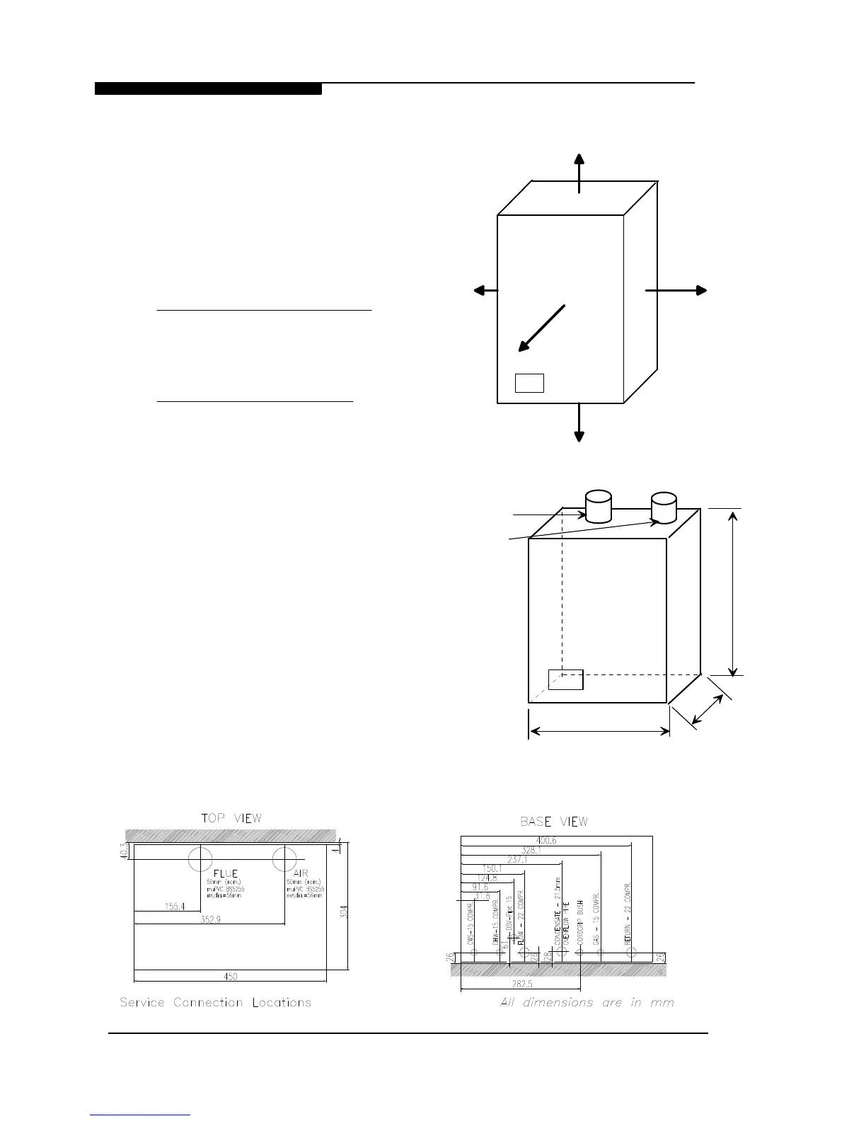
3. BOILER LOCATION
3.1 DIMENSIONS AND MINIMUM
CLEARANCES
The boiler must be installed in minimum
clearances shown to allow subsequent
servicing, and safe operation. However, larger
clearances may be required during installation.
3.2 SERVICE CONNECTIONS
Without Optional Pre-Installation Jig:
Gas, water, air and flue pipe, condensation,
and electrical connections are as shown. Gas :
15mm compression. Flow/Return 0.75BSPM
compression. DHW/CWS 0.5BSPM
compression.
With Optional Pre-Installation Jig:
Gas, water, air and flue pipe, condensation,
and electrical connections are as shown. Gas :
15mm compression. Flow/Return 22mm
compression. DHW/CWS 15mm
compression.
An optional stand-off frame is also available
which mounts behind the boiler to leave a
50mm deep space behind the boiler. This is
to permit pipe routing behind the boiler if
required. See Section 2.5 - Optional
Accessories.
3.3 POSITION
The C36 Combi and C36P Combi are not
suitable for external installation. The boiler
may be installed in any room or internal
space, although particular attention is drawn
to the requirements of the current IEE Wiring
Regulations and, in Scotland, the electrical
provisions of the Building Regulations
WD388/0/2004 Chapter 3 - Boiler Location The Keston C36 Combi & C36P Combi Boilers
Installation & Servicing Instructions Page : 9
All dimensions in mm.
150
300 When servicing appliance
100
Figure 3.1.1
Minimum Clearances
55
10 When appliance is operating