6.7.5 Exploded Diagrams Parts Reference List
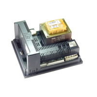
Boiler Controls Assembly (Fig. 6.7.1)
GC Number Code Description
135 Main Control Box (C.10C.4.01.00.0 A)
138 Control Panel (C.10C.4.04.00.0 A)
146 Terminal Block (C.12.4.00.03.0)
206 Terminal Block (C.10C.4.28.00.0)
E72-401 153 Thermal Fuse (C.08.4.21.00.0)
136 Ignitor Cable (C.10C.4.02.00.0)
Waterway, Condensate & Flue Assembly (Fig. 6.7.2)
GC Number Code Description
39 Heat Exchanger
(C.10C.2.01.00.1)
57 DHW Heat Exchanger (C.10C.2.09.00.0)
58 Expansion Vessel (C.08.0.08.00.0 A)
46 Burner (C.10C.2.04.00.0)
161 Burner Head Gasket
(C.10C.2.00.45.0 A)
49 Ignitor Gasket (C.10C.2.00.52.0 A)
48 Spark Electrode (C.10C.2.06.00.1)
51 Condensate Trap (C.10C.2.07.00.0)
67 Flow/Return Sensor (C.10C.2.23.00.0)
68 Flue Sensor (C.10C.2.11.00.0)
108 DHW Sensor (C.10C.2.16.00.0)
112 Pressure Sensor (C.10C.2.17.00.1)
94 Flow Sensor (C.10C.2.33.00.0)
56 Hydroblock (C.10C.2.08.00.0)
Air - Gas Assembly (Fig. 6.7.3)
GC Number Code Description
119 Combustion Blower (C.10C.3.01.00.1)
215 C36 Combi Gas Valve - Mixer Air Gas
Assembly (C.10C.3.06.00.0)
215 C36P Combi Gas Valve - Mixer Air Gas
Assembly (C.10C.3.07.00.0)
Casing Assembly (Fig. 6.7.4)
GC Number Code Description
2 Cabinet Cover (C.10C.1.02.00.0 A)
19 Databadge - NG (C.10C.1.00.06.0)
19 Databadge - LPG (C.10C.1.00.06.1)
E73-355 10 Combustion Test Plug (B.04.2.00.49.1)
WD388/0/2004 Chapter 6 : Fault Finding The Keston C36 & C36P Combi Boilers
Installation & Servicing Instructions Page : 36