4 5
Quick Setup Guide
1. Begin with the KD-HD4x4/6x6/8x8Lite and all input/output devices turned off and power
cables removed.
2. Connect HDMI sources to the appropriate input ports on the KD-HD4x4/6x6/8x8Lite.
3. Connect CAT5e/6 outputs to the KD-CATHD250POHRx extenders via CAT5e/6 cables, then
connect the extenders to the output devices (display, projector, AV Receiver, etc).
4. Connect HDMI outputs to the appropriate output device (outputs will mirror CAT5e/6).
5. Connect both power supplies (one for the Matrix and one for the POH Extenders) to the KD-
HD4x4/6x6/8x8Lite and all other input and output devices and turn them on.
6. Operate the KD-HD4x4/6x6/8x8Lite switcher via front panel buttons, IR Remote, Serial IR or
RS-232 control.
Operation:
After performing the setup above, the unit is ready for operation.
There are several options for controlling the unit. Commands can be issued via IR remote control,
RS-232, TCP/IP or by using the front panel buttons. Note that the advanced commands are
available only via the RS-232 protocol.
KD-CATHD250POHRx Baluns
If you will be utilizing the KD-CATHD250POHRx extender, please follow this procedure.
› One CAT5e/6 UTP or STP cable needs to be used.
› Use the shortest possible HDMI cable when connecting the Extender to the Display. Key Digital
recommends cables 6 ft. or shorter for optimum performance.
› Ensure the CAT cable is run directly from the switcher to the Extender.
› Do not use patch panels, punch downs, keystones, couplers, wall plates, etc..
› Key Digital recommends the use of CAT5e/6 STP cable with shielded RJ45 connectors
for optimum performance and distances from your Extender.
Extending and Routing Control Signals
› The KD-HD4x4/6x6/8x8Lite feature powerful and useful control routing features. The switchers
have the ability to matrix control signals just like they can audio and video signals.
› KD-HD4x4/6x6/8x8Lite can consolidate incoming IR/RS-232 signals to control any display/output
connected via CAT5/6 or via HDMI (control signal extension via HDMI only available with Key
Digital Commercial HiFi ProS cables).
› KD-HD4x4/6x6/8x8Lite can consolidate incoming IR/RS-232 signals to control any source/input
connected via HDMI, with Key Digital’s Commercial HiFi ProS cables.
› IR and RS-232 control signals are bi-directional, and may ow from the matrix to the zone or from
the zone to the matrix.
› The default signal path for control signals is to route IR control signals from Expansion I/O Port 1
to RJ45 output 1…Expansion I/O Port 8 to RJ45 Output 8 (the path and control signal type can
be manipulated by using the desired RS-232 command).
› When connecting the IR Emitter to the device you wish to control, make sure to nd the IRreceiver
area on the device
Control Signal Extension from External I/O Ports:
The default setting for control signal extension is to route IR signals from Expansion I/O Port 1 to
RJ45 output 1…Expansion I/O Port 8 to RJ45 Output 8 (the path and control signal type can be
manipulated by using the desired RS-232 command). When routing control signals to/from an
HDMI input/output, Key Digital’s HiFiProS cable must be used.
› Point-to-Point control routing is established by using commands containing “IRR” or “RSS”.
› Point-to-Many control routing is established by using commands containing “IR” or “RS”.
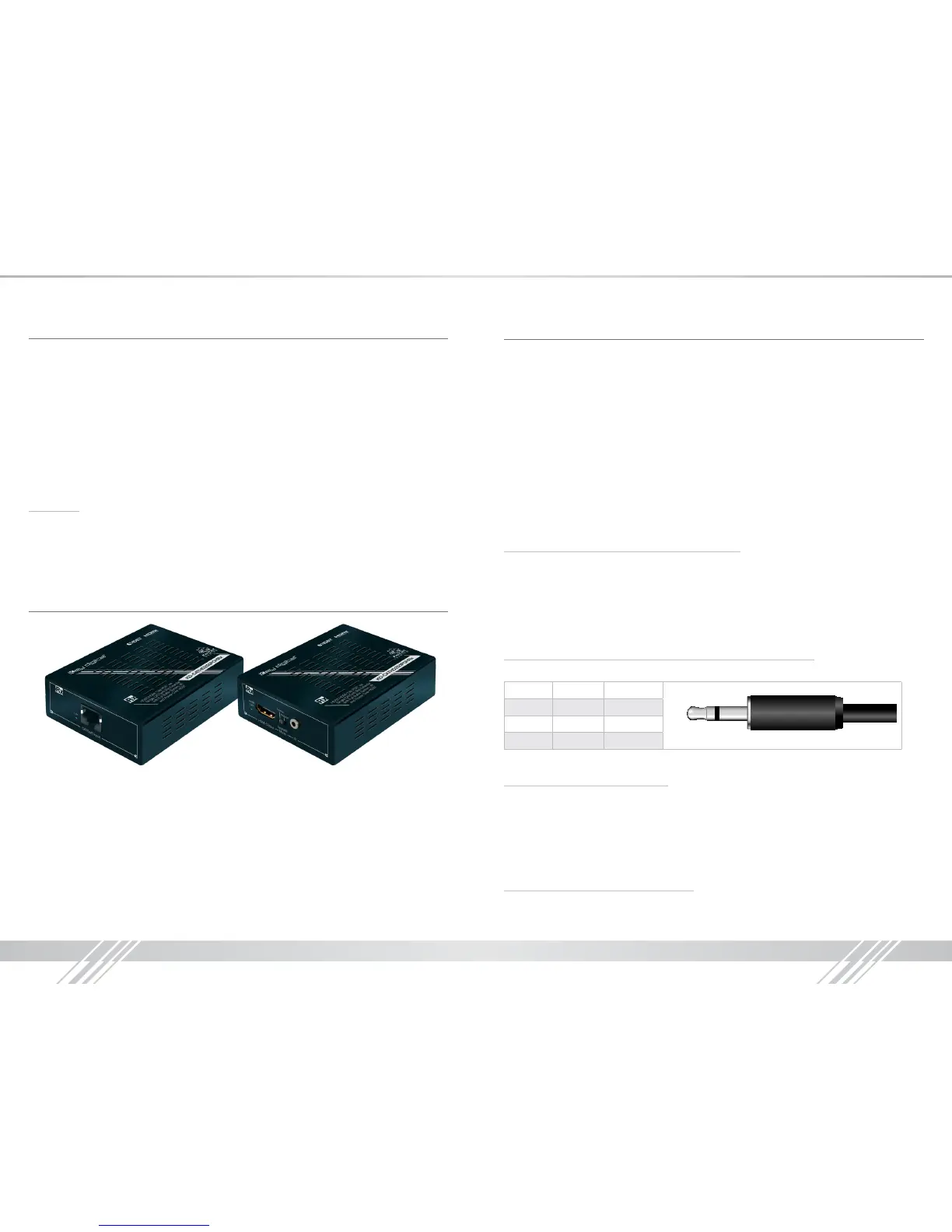
Extension I/O and Digital Audio Output (ARC) Port Conguration
Supports IR or RS-232 routing or ARC output. See chart below for 3.5mm jack conguration:
Tip Ring
IR TX or RX None
RS232 TxD RxD
ARC NONE ARC OUT
Note: If ARC is enabled, IR and RS-232 signal routing will be disabled.
Point-to-Point IR Control Routing:
› To congure the path of IR control signals from an External I/O Port to an RJ45 output, use the
command “SPOC xx IRR 1 S yy”. xx=IR destination, yy=IR source
› To congure the path of IR control signals from an External I/O Port to an HDMI output, use the
command “SPOH xx IRR 1 S yy”. xx=IR destination, yy=IR source
› To congure the path of IR control signals from an External I/O Port to an HDMI input, use the
command “SPI xx IRR 1 S yy”. xx=IR destination, yy=IR source
Point-to-Point RS-232 Control Routing:
› To congure the path of RS-232 control signals from an External I/O Port to an RJ45 output, use
the command “SPOC xx RSS 1 S yy”. xx=RS-232 destination, yy=RS-232 source
 Loading...