INSTALLATION GUIDELINE
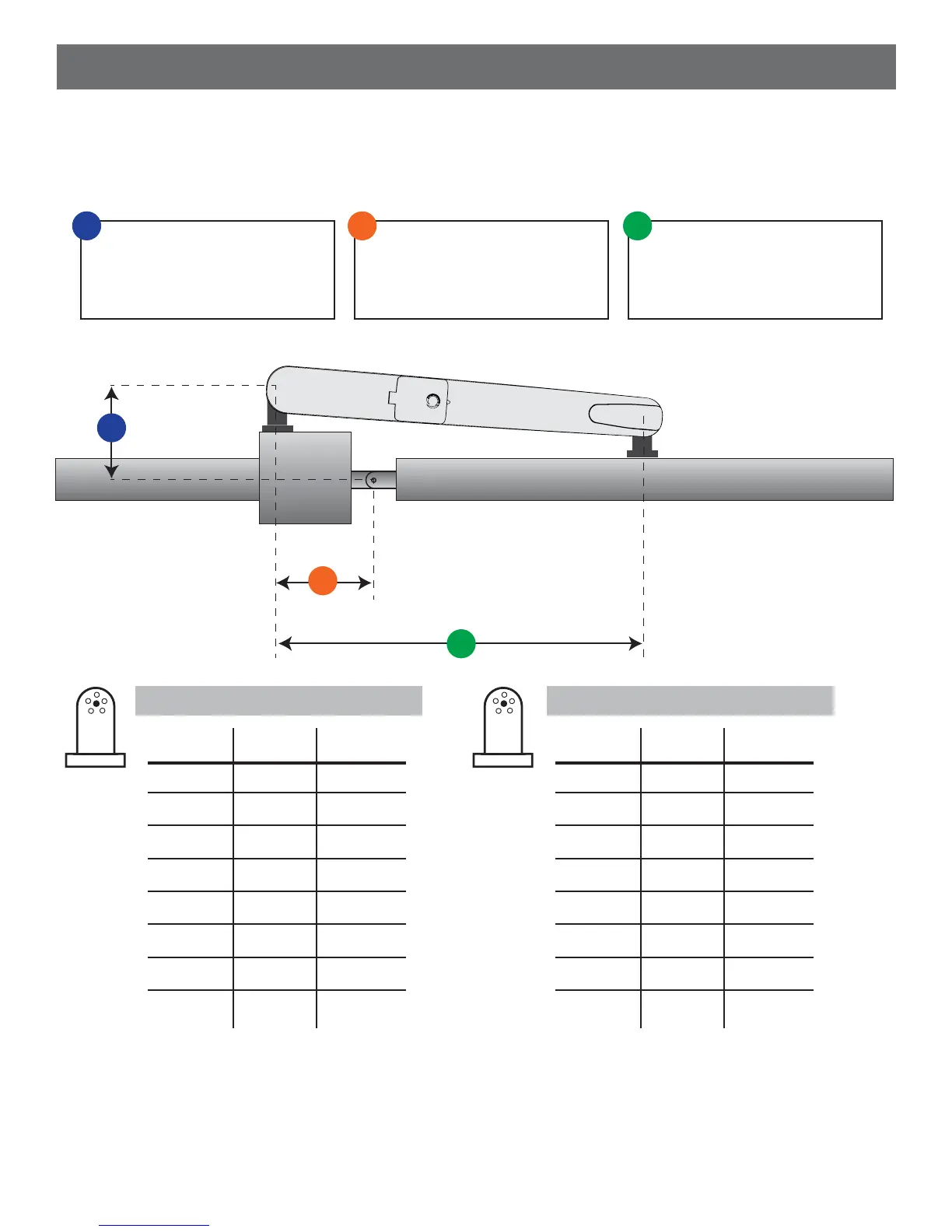
1. Measure the distance “A” from the center point of the hinge to the rear bracket hole.
2. Use the table to determine the optimum measurement for “B” and attach the rear bracket to the post.
3. Mount the front bracket so that the hole of the front bracket is 29 1/2” from the hole on the rear bracket “C”.
90°-100° OPENING
A (in)
4”
4 1/4”
4 1/2”
4 3/4”
7”
7 1/4”
7 1/2”
7 3/4”
B (in)
4”
4 1/4”
4 1/2”
4 3/4”
7”
7 1/4”
7 1/2”
7 3/4”
C (in)
29 1/2”
29 1/2”
29 1/2”
29 1/2”
29 1/2”
29 1/2”
29 1/2”
29 1/2”
Fig. 4
Measurement between the
center of the gate plane and
the rear bracket hole
Measurement between the
center of the gate hinge and
the rear bracket hole plane
Measurement between the
front and rear brackets
A
B
C
C
B
A
100°-110° OPENING
A (in)
5”
5 1/4”
5 1/2”
5 3/4”
6”
6 1/4”
6 1/2”
6 3/4”
B (in)
5”
5 1/4”
5 1/2”
5 3/4”
6”
6 1/4”
6 1/2”
6 3/4”
C (in)
29 1/2”
29 1/2”
29 1/2”
29 1/2”
29 1/2”
29 1/2”
29 1/2”
29 1/2”
Check the permitted opening angle based on the mounting points of the brackets in the charts in Fig 4.
4