c d
GEARMOTOR RELEASE
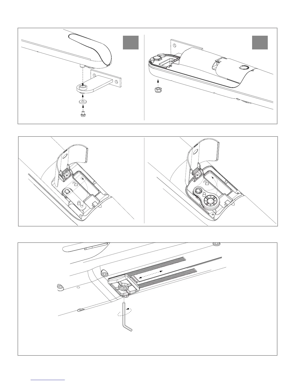
SECURING THE GEAR MOTOR AND REAR BRACKET (continued)
1
2
3
SETTING OF THE MECHANICAL LIMIT SWITCH
Fig. 7
Fig. 8
Fig. 9
Insert the pin of
the sliding bracket
into the bushing of
the front bracket and
secure it with the
screw and washer
as shown in Fig. 7c.
Tighten the screw on the
rear bracket previously mounted
with the nut as shown in Fig 7d.
Release the gear
motor as shown
in Fig. 8.
Loosen the screw on the mechanical limit switch until
it is able to slide. Open the gate manually to the
desired opening position. Bring the mechanical limit
switch up to the pin of the slide bracket and secure it
with the screw as shown in Fig. 9. If you need to
adjust the mechanical limit switch for the closing
position repeat the same procedure, this time manu-
ally bringing the gate to the desired point of closure.
6