POWER CONNECTIONS
REPLACEMENT OF THE LEDS
1
2
3
Only 24 Vdc
Fig. 10
Fig. 11
a
b
COM
M+
M-
V+
RAY4024E
LED ENCODER MOTOR
24 Vdc
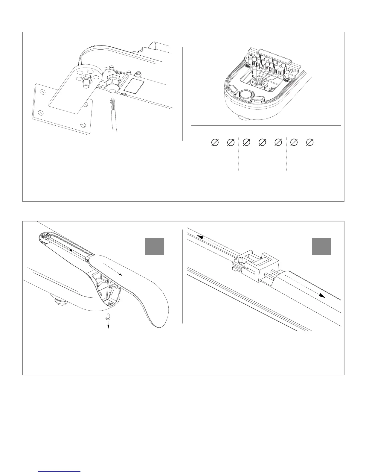
Loosen the cable and insert the power cord as
shown in Fig. 10. Connect the wires of the power
cable to the terminal block according to the wiring
diagram in Fig. 10. Screw the cable gland tight to
secure the wires. Replace the top cover - first sliding
it slightly backward, open the door and tighten the 2
screws that secure the rear cover.
Turn off the power supply. Use a screwdriver to remove the lower screw as shown in Fig. 11a. Remove
the cover and LED strip as shown in Fig. 11a. Disconnect the connector as shown in Fig. 11b. Connect
the new LEDs and insert them into the mask. Connect the mask by first inserting the side of the seal
and then securing it with the screw.
7