2
1. Introduction (2)
1-4 Specications
Type
Distance setting
Appearance
M18 Threaded Mount
Model
LR-ZH490CB
*1
Detectable distance
25 to 490 mm (465 to 0)
*2
Standard detection deviation
25 to 170 mm : 9 mm
170 to 290mm : 25mm
290 to 390mm : 40mm
390 to 490mm : 50mm
Display resolution
1 to 5 (1 to 5 mm)
Spot diameter
Approx. φ3 mm
Response time
1.5 ms/10 ms/50 ms selectable
Light source
Type
Red laser (660 nm)
Laser class
Class 2 laser product (IEC60825-1)
Class
Laser product (FDA(CDRH) Part1040.10)
Function
Indicator
3-digit 7-segment display (white),
output indicator (yellow),
DATUM indicator (orange), 1 spot indicator (green)
Timer
OFF/ON delay/OFF delay/One-shot
Specications
Power voltage
10 to 30 VDC, including 10% ripple (P-P), Class 2 or LPS
Power
consumption
450 mW or less
(18 mA or less at 24 V, 34 mA or less at 12 V)
Control output
NPN open collector/PNP open collector selectable,
Applied voltage 30 VDC or less,
Control current 100 mA or less,
Residual voltage 1.2 V or less at 10 mA or less,
2 V or less at 10 to 100 mA
Protection
circuit
Protection against reverse power connection,
output overcurrent, output surge,
reverse output connection
Output
operation
Light-ON/Dark-ON selectable
External input
Short-circuit current NPN: 1 mA or less/
PNP: 2 mA or less
For input time, refer to the time chart.
(Instruction manual page 5)
Environmental
resistance
Enclosure
rating
IP68(IEC60529)/IP69K(DIN40050-9)/
4X, 6P, 13(NEMA250)
Ambient light
*3
Incandescent lamp: 10,000 lx or less
Sunlight: 20,000 lx or less
at 240 mm
Incandescent lamp: 2,000 lx or less
Sunlight: 4,000 lx or less
at 490 mm
Ambient
temperature
−10 to +50°C (no freezing)
Storage
temperature
−25 to +75°C (no freezing)
Ambient
humidity
35 to 85%RH (no condensation)
Shock
resistance
1,000 m/s
2
in X, Y, Z axis directions respectively 6 times
Vibration
resistance
10 to 55 Hz Double amplitude 1.5 mm in the X, Y, Z
axis directions respectively, 2 hours
Insulating
resistance
20 MΩ or more (500 VDC)
Withstand
voltage
1,000 VAC 50/60 Hz 1 min
Material
Case: SUS316L, Display: PES,
Lens cover: PMMA with scratch-resistant coating,
Packing/Connector ring: FKM
Nut: SUS316L, Toothed washer: SUS304
Weight
Approx. 75 g
*1 IO-Link specication v.1.1/COM2 (38.4 kbps) is supported. (Only when PNP output is
selected.)
You can download a setup le from the KEYENCE website (http://www.keyence.com).
If you are using the product in an environment in which you cannot download les over
the Internet, contact your nearest KEYENCE ofce.
*2 Display reading used as a guide for the detecting distance. When the setting value is
tuned, the readout shifts. When the value exceeds “-99”, “-FF” is displayed.
*3 When the response time is 10 ms
1-5 Package contents
• Sensor
A connector cap is supplied with connector sensors.
• FDA warning/certication/identication label
• Laser warning/explanation labels
• Instruction Manual
• Nut
• Toothed washer
2. Installation and Wiring
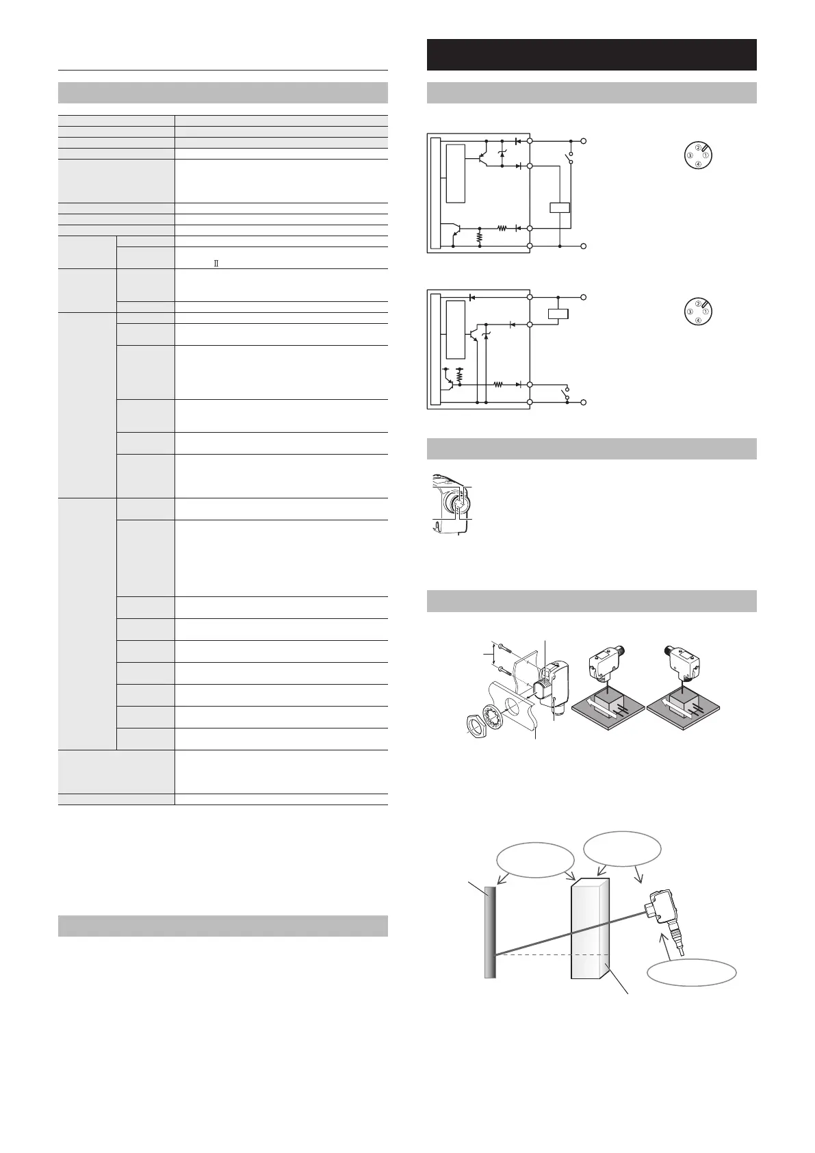
2-1 I/O Circuit Diagram
z When PNP output is selected
Overcurrent
protection circuit
Brown/1
White/2
10 to 30 VDC
0 V
Black/4
Blue/3
Load
Sensor main circuit
M12 connector (4-pin) type
z When NPN output is selected
Brown/1
Black/4
10 to 30 VDC
0 V
White/2
Blue/3
PLC, etc.
3 VDC
Overcurrent
protection circuit
Sensor main circuit
Load
M12 connector (4-pin) type
2-2 Wiring
1 : 10 to 30 V
2 : OUT (NPN)/IN (PNP)
3 : 0 V
4 : OUT (PNP)/IN (NPN)
M12 Connector tightening torque: 0.8 Nm
* Tighten the connector by a hand, and then retighten it by using tools and so on.
Insufcient tightening will degrade water-resistant performance.
2-3 Installation
24.1 mm
Tightening
torque: 0.6 Nm
or less
M18 Tightening torque:
20 Nm or less
Direction of installation
3 mm or less
φ3.2
OK NG
If detection is unstable
• When detecting transparent targets, move the sensor as close as possible to the
workpiece, and move the workpiece as far away as possible from the background for
increased stability.
• Tilt the optical axis of the sensor as much as possible in reference to the background
surface. (10° or more)
Reference
surface
Separate as far
apart as possible.
Move as close
as possible.
Tilt the beam axis
downward.
Transparent object
• For thin objects or transparent objects, use of “Universal Change Detection” is
recommended. (See “ Universal Change Detection” (page 3))
• If the sensor is affected by ambient light, install a light blocking plate, or change the
installation location.